
- Catalogs
- ELETTROTEC s.r.l.
- Float level switches


Float level switches

Float level switches
Elettrotec reserves the right to modify technical data or discontinue products without notice. Users must verify product suitability for specific applications through field tests.
Elettrotec's float level switches are designed for liquid level monitoring in various applications. They offer models with one to four floats, customizable lengths up to 2500 mm, and materials such as aluminum, thermoplastic, PVC, NBR, Nylon, Hostaform, brass, and stainless steel. Mounting options include flanges and threaded plugs, with explosion-proof models available per ATEX Directive 94/9/EC.
Suitable for hydraulics, pharmaceuticals, water treatment, industrial vehicles, and more. Marine-certified models are available.
Switches use a reed switch actuated by a magnetic field from a float, mountable vertically or at an angle up to 15°.
- Max fluid viscosity: 150 cSt
- Max pressure: 10 bar
- Fluid specific gravity: ≥ 0.7
- Electrical connection: PG09 – DIN43650
- Electrical protection: IP65 – DIN40050
- Operating temperature: -10°C to +80°C
- Max temperature with FKM gasket and Silicone cable: +130°C
Reed switches are hermetically sealed, available in SPST or SPDT configurations, with varying electrical ratings.
For inductive loads, use a semiconductor diode for DC circuits and an RC link for AC circuits. For capacitive loads, use resistors to limit current peaks.
Switching voltage and current combinations must not exceed rated power. Additional protective circuits may be required for inductive or capacitive loads.
- Switching Capacity: DC 60 W, AC 60 VA for general models; DC 10 W, AC 10 VA for NC contact versions; DC 3 W, AC 3 VA for SPDT and NO contact versions.
- Current: 0.8 A (resistive) for general models; 0.5 A for NC contact versions; 0.25 A for SPDT and NO contact versions.
- Voltage: Maximum working voltage of 220 V - 50 Hz, with breakdown voltages of 300 V for general models and 200 V for SPDT and NO contact versions.
- Insulation Resistance: 1010 Ohm for general models; 109 Ohm for SPDT and NO contact versions.
- Temperature Range: -10°C to +80°C.
- Maximum Pressure: 5 Bar for general models; 10 Bar for stainless steel versions.
- Fluid Viscosity: Maximum of 150 cSt.
- Level switches should be mounted vertically on the tank cover, with the float at least 50 mm away from metal walls.
- For inductive loads, a protection circuit is required to prevent damage.
- Users must verify the suitability of the products for specific applications through field tests.
- For inductive loads, use an RC link or semiconductor diode for protection.
- For lamp loads, connect resistance in series or parallel to the switch to preheat lamp filaments.
- LEM5: General use with black nylon body and NBR float.
- LEM5A: Nontoxic version for food and beverage applications, with a white body and stainless steel float.
- LEM6: Similar to LEM5 but with different contact specifications.
- LEM6A: Nontoxic version of LEM6.
- LEM7: Stainless steel version for higher pressure applications.
Elettrotec reserves the right to modify product specifications or discontinue products without prior notice. Users are responsible for ensuring product compatibility and suitability for their specific applications.
- Maximum Operating Voltage: 220 V - 50 Hz
- Breakdown Voltage: 300 Vdc
- Open Contact Capacitance: 0.2 pF
- Insulation Resistance: 1010 Ohm
- Switching Power in DC: 3 W
- Switching Power in AC: 3 VA
- Current Intensity: 0.25A (resistive)
- Maximum Operating Voltage: 175 Vdc
- Breakdown Voltage: 200 Vdc
- Open Contact Capacitance: 1 pF
- Insulation Resistance: 109 Ohm
- Temperature Range: -10° to +80°C
- Maximum Pressure: 10 Bar
- Fluid Specific Gravity: ≥ 0.7
- Max. Fluid Viscosity: 150 cSt
This series of electromagnetic level switches is designed to monitor the fluid level in a tank and send an electric signal if the fluid exceeds or falls below set levels. They should be installed vertically on the tank cover, with the float at least 50 mm away from metal walls.
- Brass Fitting and Tube: NBR float
- Models: Supplied with standard 1000 mm lead wires
Ensure proper fastening of fittings to prevent leakage and ensure correct operation. For inductive loads, a protection circuit is required.
Elettrotec reserves the right to modify technical data or discontinue products without notice. Users must verify product suitability for specific applications through field tests.
This document provides technical specifications and usage guidelines for electromagnetic float level switches designed to monitor fluid levels in tanks and send electrical signals when levels deviate from set points. The document includes specifications for both standard and stainless steel models, with details on installation, electrical characteristics, and material compatibility.
- Stem Length: Maximum 2500 mm
- Switching Capacity: 60 W in DC, 60 VA in AC
- Current: 0.8 A (resistive)
- Voltage: 220 V - 50 Hz
- Breakdown Voltage: 300 V
- Insulation Resistance: 1010 Ohm
- Temperature Range: -10 to +80°C
- Maximum Pressure: 10 Bar
- Fluid Viscosity: Maximum 150 cSt
- Material: Anodized aluminum, brass, bronze, NBR, and stainless steel AISI 316
The switches should be mounted vertically on the tank cover, ensuring the float is at least 50 mm away from metal walls. For inductive loads, a protection circuit is recommended.
When ordering, specify the model and dimensions (A, B, C, D). Minimum contact distance is 90 mm. Custom lengths up to 2500 mm are available upon request.
Models are available in compliance with ATEX Directive 94/9/EC for intrinsic safety, marked II 1/2 G Ex ia IIB T6.
Elettrotec reserves the right to modify technical data or discontinue products without notice. Users must verify product suitability for specific applications through field tests.
Catalog excerpts

Livellostati elettromagnetici Float level switches CONTROL DEVICES FOR FLUIDS
Open the catalog to page 1
LIVELLOSTATI ELETTROMAGNETICI I livellostati ELETTROTEC sono stati studiati per soddisfare le più svariate esigenze applicative nel campo del controllo del livello di liquidi. L’ampia gamma offerta sia di modelli standard, con uno o due galleggianti, che di esecuzioni customizzate assicura massima flessibilità nella scelta e garantisce la possibilità di trovare sempre la soluzione più adatta alle proprie necessità, anche le più specifiche. Le esecuzioni speciali sono disponibili sia con un singolo punto di intervento/galleggiante che fino ad un massimo di quattro galleggianti (a seconda dei modelli)...
Open the catalog to page 2
DATI TECNICI GENERALI Max viscosità fluido: 150 cSt Pressione massima: 10 bar Peso specifico: ≥ 0,7 Connessione elettrica: PG09 – DIN43650 Protezione elettrica: IP65 – DIN40050 Temperatura di lavoro: -10°C…+80°C Temperatura max con guarnizioni FKM e cavi Silicone: +130°C GENERAL SPECIFICATIONS Max. fluid viscosity: 150 cSt Max. pressure: 10 bar Fluid specific gravity: ≥ 0.7 Electrical connection: PG09 – DIN43650 Electrical protection: IP65 – DIN40050 Operating temperature: -10°C…+80°C Max temperature with FKM gasket and Silicone cable: +130°C DATI ELETTRICI Le ampolle reed utilizzate nei livellostati...
Open the catalog to page 3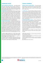
INFORMAZIONI TECNICHE TECHNICAL INFORMATION CIRCUITI PROTETTIVI PER CONTATTI REED I valori relativi alla portata della corrente e della tensione, indicati nei dati tecnici si riferiscono a carichi resistivi puri. Spesso, tuttavia, si devono controllare carichi induttivi o capacitivi, oppure si devono azionare lampade. Per situazioni di questo tipo è necessaria qualche considerazione circa l’opportunità di proteggere i contatti reed dai picchi di tensione o di corrente. 1) Carichi induttivi In presenza di circuiti alimentati con corrente continua, la protezione del contatto è relativamente facile....
Open the catalog to page 4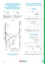
Monogramma per determinare la soppressione dell’arco di contatto per carichi induttivi Graph for determining the contact arc suppression for inductive loads Esempio 1: Esempio 2: Quando la scarica di corrente è critica, la resistenza dovrebbe essere determinata con il monogramma più basso, ad esempio: scarica di corrente 0,5 A Rmin = 400 Ω Circuiti protettivi per contatti Reed Protective circuits for Reed contacts Carichi induttivi Inductive loads Example 2: When the inrush current is critical, the resistance should be determined with the lower graph, for example inrush current 0.5 A Rrm=400...
Open the catalog to page 5
LIVELLOSTATI ELETTROMAGNETICI Float level switches LEM5 G 1/4” G 1/4” Magnete Magnet Magnete Magnet Cavetti Ig. 500 mm Lead wires Cavetti Ig. 500 mm Lead wires Cavetti Ig. 500 mm Lead wires Arresto Stop ring Arresto Stop ring SPDT CONTACT Arresto Stop ring SPDT CONTACT IMPIEGO Sono stati studiati per controllare il minimo o il massimo livello di olio, acqua, solventi contenuti in un serbatoio e per inviare a distanza un segnale elettrico. A seconda dei tipi, devono essere montati verticalmente sul coperchio del serbatoio in modo che il galleggiante disti almeno 50 mm dalle pareti metalliche....
Open the catalog to page 6
LIVELLOSTATI ELETTROMAGNETICI - ATOSSICI Float level switches - Nontoxic LEM5…A G 1/4” G 1/4” Cavi Ig. 500 mm Lead wires Cavi Ig. 500 mm Lead wires Cavi Ig. 500 mm Lead wires Arresto Stop ring Magnete Magnet Magnete Magnet Ø34 Arresto Stop ring SPDT CONTACT Arresto Stop ring SPDT CONTACT IMPIEGO Sono stati studiati per controllare il minimo o il massimo livello di un liquido in un serbatoio e inviare a distanza un segnale elettrico. Particolarmente indicati per applicazioni in campo alimentare. A seconda dei tipi, devono essere montati verticalmente sul coperchio del serbatoio in modo che il...
Open the catalog to page 7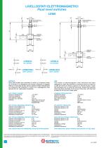
LIVELLOSTATI ELETTROMAGNETICI Float level switches LEM6 G 1/8” G 1/8” Cavi Ig. 500 mm Lead wires Cavi Ig. 500 mm Lead wires 4 Magnete Magnet Arresto Stop ring Ø8.5 Magnete Magnet Arresto Stop ring Ø8.5 SPDT CONTACT IMPIEGO Sono stati studiati per controllare il minimo o il massimo livello di un liquido in un serbatoio e per inviare a distanza un segnale elettrico. A seconda dei tipi, devono essere montati verticalmente sul coperchio del serbatoio in modo che il galleggiante disti almeno 50 mm. dalle pareti metalliche. USE This series of electromagnetic level switches has been designed to check...
Open the catalog to page 8
LIVELLOSTATI ELETTROMAGNETICI - ATOSSICI Float level switches - Nontoxic 10 Cavi Ig. 500 mm Lead wires Cavi Ig. 500 mm Lead wires 4 Magnete Magnet Arresto Stop ring Ø8.5 Magnete Magnet Arresto Stop ring BLACK SPDT CONTACT IMPIEGO Sono stati studiati per controllare il minimo o il massimo livello di un liquido in un serbatoio e per inviare a distanza un segnale elettrico. Particolarmente indicati per applicazioni in campo alimentare. A seconda dei tipi, devono essere montati verticalmente sul coperchio del serbatoio in modo che il galleggiante disti almeno 50 mm. dalle pareti metalliche. USE This...
Open the catalog to page 9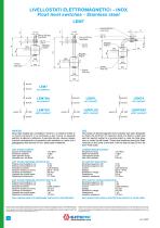
LIVELLOSTATI ELETTROMAGNETICI - INOX Float level switches - Stainless steel LEM7 Magnete Magnet Ø9 Arresto Stop ring Magnete Magnet Cavi Ig. 500 mm Lead wires Cavi Ig. 500 mm Lead wires Cavi Ig. 500 mm Lead wires Arresto Stop ring Arresto Stop ring BLACK BLACK SPDT CONTACT SPDT CONTACT SPDT CONTACT IMPIEGO Sono stati studiati per controllare il minimo o il massimo livello di un fluido contenuto in un serbatoio e per inviare un segnale elettrico di allarme a distanza. A seconda dei tipi, devono essere montati verticalmente sul coperchio del serbatoio in modo che il galleggiante disti almeno 50...
Open the catalog to page 10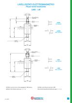
LIVELLOSTATI ELETTROMAGNETICI Float level switches LMD - LM G 1/8” conico Cavi Ig. 500 mm Lead wires Ch 12 SW 12 BLACK Magnete Magnet SPDT CONTACT Arresto Stop ring G 1/8” conico Cavi Ig. 500 mm Lead wires Ch 14 SW 14 BLACK Arresto Stop ring SPDT CONTACT MATERIALI: raccordo e tubo in ottone, galleggiante in NBR espansa. MATERIAL: brass fitting and tube; float in NBR. IMPIEGO E DATI TECNICI (vedere pag. 2 - 3 - 4 - 5). APPLICATION AND SPECIFICATIONS (see pages 2 - 3 - 4 - 5).
Open the catalog to page 11All ELETTROTEC s.r.l. catalogs and technical brochures
 CONTROL DEVICES FOR FLUIDS
6 Pages
 Flow meters and switches
19 Pages
 Pressure and Vacuum switches
67 Pages
 Temperature switches
13 Pages
 PSM 2/10...B
4 Pages
 PSM-PSP
4 Pages
 MS / PS
4 Pages
 PMM
PMM4 Pages
 PMN
PMN3 Pages

- Flowmeter
- Volume flow monitor
- Liquid flow monitor
- Liquid level detector
- Waterproof flow meter
- Gas flow monitor
- Level probe
- Stainless steel flow monitor
- Liquid level sensor
- Pressure switch
- Water flow monitor
- Mechanical pressure switch
- Analog level sensor
- Waterproof pressure switch
- Stainless steel level detector
- IP65 flow monitor
- Threaded level switch
- Diaphragm pressure switch