

VMH

VMH
The VMH type valve is a safety shut-off valve designed for gas applications, utilizing a hydraulic actuator. It is suitable for controlling air or gas flow in various appliances, with each model having a specific maximum operative pressure.
Constructed from aluminum alloy, the valves are suitable for air and non-aggressive gases, available in sizes DN65 to DN300. They are designed to close immediately upon power loss, ensuring safety. Features include a fine mesh filter, pressure gauges, and IP65 protection rating. They are tested for mechanical, chemical, and thermal conditions.
The VMH valve operates using auxiliary power. It remains closed when de-energized due to a spring mechanism and opens when the actuator is energized by hydraulic pressure. It is commonly used in industrial gas trains.
Options include a closed position indicator switch and explosion-proof versions for Zone 2. Special versions for aggressive gases are available, requiring compatibility checks.
Connections are flanged PN16, with voltage ratings of 230 VAC or 110 VAC. The operational temperature range is -15°C to +60°C. Materials in contact with gas include aluminum alloy, brass, and stainless steel.
The document provides a formula for converting air flow to other gases and details pressure drop calculations, including a specific example for a VMH8 valve.
The valves comply with European regulations for gas appliances and pressure equipment, meeting standards for electromagnetic compatibility, low voltage, and RoHS II, with ISO 9001 quality management certification.
Valves are ordered by type, connection size, operative pressure, supply voltage, and special versions. Example: VMH93.BK for a DN125 valve suitable for bio and coke gas.
Proper installation and servicing are crucial for safe operation. Detailed instructions are provided for piping and electrical connections, emphasizing leak and functional tests post-installation. Flow rate adjustments are possible for certain models, and a closed position indicator switch can be mounted.
An annual external inspection is recommended for optimal performance. Due to seal aging, valve replacement is advised after 10 years from the manufacture date.
- Turn off all power before servicing.
- Inspect the plug and replace the gasket if deteriorated.
- Ensure electrical connections are clean, dry, and tight.
- Check pipe connections for leaks using a soap solution.
- Verify valve operation by powering the actuator to open and close the valve.
- If the pump restarts more than three times in 20 minutes, replace the actuator.
- Conduct only if the valve malfunctions.
- Ensure no pressure is inside the valve before inspection.
- Remove screws on the counter flange carefully, noting the spring inside.
- Inspect and replace the main O-ring if necessary.
- Clean the assembly with compressed air and check for corrosion.
- Replace deteriorated sealing gaskets and clean the sealing lip with a cloth.
- Remove and clean the filter with compressed air.
- Reassemble the valve and check for leaks using a soap solution.
- Confirm the actuator is the failure cause before replacement.
- Ensure an identical spare part is available.
- Switch off power and remove the plug.
- Remove connecting screws and the damaged actuator, noting the O-ring.
- Reassemble the new actuator in reverse order and replace the plug if necessary.
- Read Installation and Service Instructions carefully to prevent damage and danger.
- Turn off all power before servicing.
- Perform leak and functional tests after mounting.
- Use all gaskets properly to avoid voiding the warranty.
- Ensure all wiring complies with local and national codes.
- All work must be performed by qualified technicians in compliance with codes.
Catalog excerpts

VMH Safety shut off valves for gas with hydraulic actuator DN65 … DN300
Open the catalog to page 1
ELEKTROGAS – Technical Sheet EE175 - 1020 Special versions and optionals …………………… Technical specifications …………………………… Gas flow chart (pressure drop) …………………… Elektrogas® is a brand name of ELETTROMECCANICA DELTA S.p.A. Via Trieste, 132 - 31030 Arcade (TV) - Italy Tel +39 0422 874068 Fax +39 0422 874048 www.delta-elektro
Open the catalog to page 2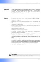
ELEKTROGAS – Technical Sheet EE175 - 1020 The VMH type valve is a safety shut off valve for gas with hydraulic actuator. It is suitable for air or gas blocking and releasing controls, required in the main pipe of gas power burners, atmospheric See Tab. 2 for maximum operative pressure for every model. The valves are made of aluminum alloy with a range for connections from DN 65 up to DN 300. Pipe connections meet group 2. Suitable for use with air and non-aggressive gases included in the 1st, 2nd and 3rd families (EN 437). Special versions for aggressive gases. The valve is open only when energized:...
Open the catalog to page 3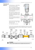
ELEKTROGAS - Technical Sheet EE175 - 1020 ELEKTROGAS - Technical Sheet EE175 - 1020 Functioning and application The VMH type valve is a safety shutting device using auxiliary power supply. When it is de-energized, the spring pushes on the seal disc, keeping the gas passage closed. In this condition the inlet chamber is filled with pressurized gas that forces on the disc, improving the seal. When the actuator is powered, the relief valve closes, the pumps starts and the pressurized oil pushes the piston. The disc opens against the combined force of spring and gas pressure. When the disc reaches...
Open the catalog to page 4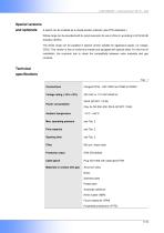
ELEKTROGAS - Technical Sheet EE175 - 1020 ELEKTROGAS - Technical Sheet EE175 - 1020 Special versions and optionals A switch can be installed as a closed position indicator (see PCS datasheet ). Whole range can be provided with Ex-proof execution for use in Zone 2, according to 2014/34/UE Directive (ATEX). The whole range can be supplied in special version suitable for aggressive gases (i.e. biogas, COG). This version is free of nonferrous metals and equipped with special seals. For this kind of installation, the customer has to check the compatibility between valve materials and gas contents....
Open the catalog to page 5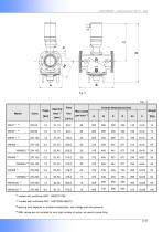
ELEKTROGAS - Technical Sheet EE175 - 1020 1 models with certificate GAR - 0063CO1798 *2 models with certificate PED - 0497/2638-2664/13 *3 opening time depends on ambient temperature, real voltage and inlet pressure *4 VMH valves are not suitable for very high number of cycles, as used in pulse firing.
Open the catalog to page 6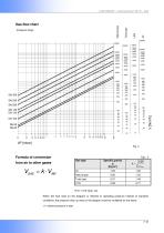
ELEKTROGAS - Technical Sheet EE175 - 1020 (Pressure drop) Formula of conversion from air to other gases VGAS = k VAIR When the flow read on the diagram is referred to operating pressure instead of standard conditions, the pressure drop Ap read on the diagram must be multiplied for the factor: (1+ relative pressure in bar)
Open the catalog to page 7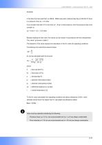
ELEKTROGAS - Technical Sheet EE175 - 1020 In the flow chart we read that in a VMH8 - DN80 valve with a Natural Gas flow of 200 Nm3/h there is a pressure drop Ap = 4,0 mbar. If we consider that 200 m3/h is the flow at 1. 5 bar of inlet pressure, then the pressure drop to be consider is: Ap = 4,0x(1 + 1,5) = 10,0 mbar Besides reading the flow chart, the valves can be chosen in accordance with the characteristic ”Kvs value” as shown in table 2. The selection of the valve requires the calculation of the Kv under the operating conditions. Considering only subcritical pressure drops: Kv can be calculated...
Open the catalog to page 8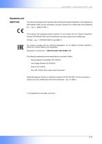
ELEKTROGAS – Technical Sheet EE175 - 1020 The valves are designed and manufactured according to European Regulation on Gas appliances 2016/426/UE (GAR) and the certification has been issued by the notified body Kiwa Nederland B.V. – reg. n° 0063CO1798 (*). The products with operating pressure superior 0.5 bar comply with the Pressure Equipment Directive 2014/68/UE (PED) and the certification has been issued by the notified body: CSI Spa – reg. n° PED/0497/2638/13 and 2664/13. The product complies with the Technical Regulations TP TC 004/2011-016/2011-020/2011032/2013 of Russia, Belarus and Kazakhstan....
Open the catalog to page 9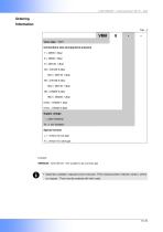
ELEKTROGAS – Technical Sheet EE175 - 1020 Valve type VMH Connections size and operative pressure 7 = DN65 1.6bar 8 = DN80 1.6bar 9 = DN100 1.3bar 93 = DN125 0.5bar 93U = DN125 1.3bar 95 = DN150 0.5bar 95U = DN150 1.3bar 98 = DN200 0.2bar 98U = DN200 1.3bar 910U = DN250 1.3bar 912U = DN300 0.6bar Supply voltage - = 230V 50/60Hz B = 110V 50/60Hz Special version J = version for bio gas K = version for coke gas Example: VMH93.BK : valve DN125, 110V suitable for bio and coke gas ▪ Optionals available: explosion-proof execution, PCS (closed position indicator switch), others on request. They must be...
Open the catalog to page 10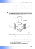
ELEKTROGAS – Technical Sheet EE175 - 1020 Installation, adjustment and service To assure a proper and safe operation, as well as a long life of the valve, installation procedure and periodical servicing are very important topics and the following instructions should be always fulfilled. IMPORTANT: before proceeding with the installation, ensure that all the features of your system comply with the specifications of the valve (gas type, operating pressure, flow rate, ambient temperature, electrical voltage, etc.). CAUTION Shut off the gas supply at the main manual shut-off valve and disconnect...
Open the catalog to page 11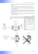
ELEKTROGAS - Technical Sheet EE175 - 1020 - Remove the end caps and make sure no foreign body is entered into the valve during handling. - Position the gasket or sealing agent on the flanges and insert the bolts with washers. - Screw the nuts tightening them crosswise and using proper tools only. Avoid overtightening and mount tension free. - If the actuator has been removed, check the correct position of the O-ring and position the actuator on its connection flange (in case of vertical pipe the actuator must be oriented with the plug upward). - Fit all the screws with washers and then screw...
Open the catalog to page 12All Elettromeccanica Delta S.p.A. catalogs and technical brochures
 General Catalogue
44 Pages
 VMERNA
7 Pages
 vmm
vmm11 Pages
 VML
VML11 Pages
 VMR
VMR11 Pages
 FG Gas filter
9 Pages
 PSG Pressure Switch for Gas
6 Pages
 VF-VFH Butterfly valves
12 Pages
 A-AD aluminium pump
6 Pages
 EV oil valve
3 Pages


