
- Catalogs
- ELESTA GmbH
- Product catalogue 2014 - Relays with forcibly guided contacts

- Company
- Products
- Catalogs
- News & Trends
- Exhibitions
Product catalogue 2014 - Relays with forcibly guided contacts

Product catalogue 2014 - Relays with forcibly guided contacts
ELESTA GmbH, founded in 1997, has grown into a global leader in functional safety and relay technology, employing over 250 people. The company is dedicated to innovation and quality, producing relays and sensors crucial for safety circuits across various industries.
ELESTA prioritizes research and development, fostering innovation through a robust internal think tank. The company employs lean management principles to boost production efficiency and competitiveness, with strong employee engagement reflected in numerous continuous improvement suggestions.
The catalogue features relays with forcibly guided contacts, emphasizing their compact size, high shock resistance, large excitation voltage, low coil power loss, and high switching reliability. These relays are suitable for various applications, including ATEX areas, and offer configurations for different load requirements.
Relays are available with various contact numbers, materials, and types, supporting coil voltages from 3 VDC to 220 VDC. They have different coil capacities and switching current ranges, with specified test voltages ensuring safety and reliability.
The relays are compact and approved by UL, cUL, and TÜV, ensuring compliance with international standards.
ELESTA's dedication to quality and innovation is evident in its products, designed to meet the highest safety and performance standards in the industry.
Key specifications include a test voltage of 4000 V / 50 Hz / 1 min, creepage resistance of CTI 175, pollution degree 2, overvoltage category III, and insulation resistance at Up 500 VDC greater than 100 MΩ. The relay has a mechanical endurance of over 10 million operations and a switching frequency of 15 Hz.
The relay features basic insulation at 250 VAC with air and creepage distances greater than 4 mm, and double or reinforced insulation at 250 VAC with distances greater than 5.5 mm, tested at 4000 V / 50 Hz / 1 min.
Contact material is AgCuNi+0.2-0.4 µm Au, with a rated switching capacity of 250 VAC 6 A AC1 1500 VA. The electrical life is over 90,000 cycles, with a maximum inrush current of 30 A for 20 ms.
The relay complies with UL File E188953 Sec. 5, insulation class IEC 60664-1 250 VAC, and fire protection requirements UL 94 / V0.
According to DIN EN60947-5-1, the relay supports AC 1: 250 V / 6 A, AC 15: 230 V / 3 A, DC 1: 24 V / 6 A, and DC 13: 24 V / 5 A / 0.1 Hz.
The relay is a PCB type with forcibly guided contacts, offering protective separation between control and load circuits with leakage and creepage distances greater than 8 mm. It features double and reinforced insulation between contacts and small external dimensions.
Standard coils for direct current are available with nominal voltages from 5 VDC to 110 VDC, with specific values for minimum pick-up voltage, drop-out voltage, nominal current, and resistance at 20°C.
The relay operates within an ambient temperature range of -40°C to +70°C, with a thermal resistance of 50 K/W. It is resistant to shock and vibration, with specific values for NO and NC contacts.
Available options include PCB sockets, DIN rail sockets, and various modules, with the product key for ordering being SGR282ZK 24VDC.
Detailed information is provided on contact lifetime for NO contacts under various conditions and maximal switching characteristics according to DIN EN60947-5-1.
The relay has specific dimensions in millimeters and can be mounted in any position, with a type of protection RT II and a solder bath temperature of 270°C for 5 seconds.
Catalog excerpts

Product Catalogue Relays with forcibly guided contacts
Open the catalog to page 1
Product Catalogue - Relays with forcibly guided contacts Edition 05/2015 Publisher: ELESTA GmbH, Bad Ragaz, Switzerland All rights reserved. This work and its parts are protected by copyright. Any use in other than legally authorized cases requires the prior written consent of the publisher.
Open the catalog to page 2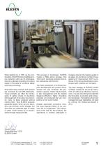
What started out in 1997 as the continuation of ELESTA AG‘s traditional relay production with just 15 employees, became a globally operating innovation leader in the area of functional safety and relay technology. Now latest relay products and sensors are produced by over 250 employees. These products are often the centrepiece of safety circuits of machinery and equipment. Every day we encounter many of those products without noticing them. Thus ELESTA products guarantee safety when we use elevators, ride the train, at the hospital, but also when we celebrate stars on stage or when movie heroes...
Open the catalog to page 3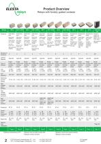
Product Overview Relays with forcibly guided contacts Relays Features Small dimensions Small dimensions Small dimensions Small dimensions High shock resistance High shock resistance High shock resistance High shock resistance Large excitation voltage Very large excitation voltage Large excitation voltage Very large excitation voltage Low coil power loss Very low coil power loss High switching High switching reliability reliability High switching Very low coil reliability power loss High switching reliability Extremely at Extremely at Extremely at Extrusioncoated coil design design design design...
Open the catalog to page 4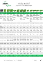
Product Overview Relays with forcibly guided contacts Extremely Powerful powerful High switching High switching High switching reliability reliability Small design High switching High switching High switching High switching reliability Wide coil Wide coil reliability For loads with reliability reliability Large switch- reliability working range working range For the highest a high surge ing current High switching High switching High switching High switching Low coil Contact Low coil loads during current range reliability reliability reliability reliability Contact Contact power loss assignment...
Open the catalog to page 5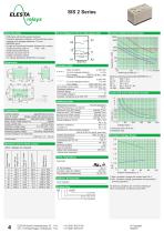
Circuit Diagram (view on relay upper side) - PCB Relay with forcibly guided contacts - Protective separation between control and load curcuit (leakage and creepage distances >10 mm) - EN50205 type A - Double and reinforced insulation between the contacts - Contact mounting: SIS112 1 NO / 1 NC - Small external dimensions - Nominal coil power 0,27 W - Holding coil power 0,08 W - For railway application (EN50155) on request Basic insulation at 250 VAC Air and creepage distance >4 mm Test voltage 2500 V / 50 Hz / 1 min Double or reinforced insulation at 250 VAC - Air and creepage distance >10 mm...
Open the catalog to page 6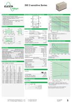
Circuit Diagram (view on relay upper side) - PCB Relay with forcibly guided contacts - Protective separation between control and load curcuit (leakage and creepage distances >10 mm) - EN50205 type A - Double and reinforced insulation between the contacts - Contact mounting: SIS112 1 NO / 1 NC - Small external dimensions - Nominal coil power 0,2 W - Holding coil power 0,04 W Basic insulation at 250 VAC Air and creepage distance >4 mm Test voltage 2500 V / 50 Hz / 1 min Double or reinforced insulation at 250 VAC - Air and creepage distance >10 mm - Test voltage 5000 V / 50 Hz / 1 min Test voltage...
Open the catalog to page 7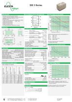
Circuit Diagram (view on relay upper side) - PCB Relay with forcibly guided contacts - Protective separation between control and load curcuit (leakage and creepage distances >8 mm) - EN50205 type A - Double and reinforced insulation between the contacts - Contact mounting: SIS212 2 NO / 1 NC - Small external dimensions - Nominal coil power 0,6 W - Holding coil power 0,18 W - For railway application (EN50155) on request Insulation Data Contact Lifetime for NO contacts Basic insulation at 250 VAC Air and creepage distance >4 mm Test voltage 2500 V / 50 Hz / 1 min Double or reinforced insulation...
Open the catalog to page 8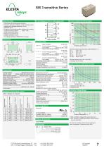
Circuit Diagram (view on relay upper side) - PCB Relay with forcibly guided contacts - Protective separation between control and load curcuit (leakage and creepage distances >8 mm) - EN50205 type A - Double and reinforced insulation between the contacts - Contact mounting: SIS212 2 NO / 1 NC - Small external dimensions - Nominal coil power 0,4 W - Holding coil power 0,14 W - For railway application (EN50155) on request Insulation Data Contact Lifetime for NO Contacts Basic insulation at 250 VAC Air and creepage distance >4 mm Test voltage 2500 V / 50 Hz / 1 min Double or reinforced insulation...
Open the catalog to page 9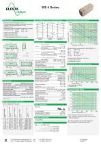
Circuit Diagram (view on relay upper side) Contact Data Contact material AgCuNi+0,2-0,4 µm Au Type of contact Single contact with notched crown Rated switching capacity 250 VAC 6 A AC1 1500 VA Electr. life AC 1(360 cycles / h) >90000 Inrush current max. 30 A for 20 ms Switching voltage range 5 to 250 VDC / VAC Switching current range* 3 mA to 6 A Switching capacity range* 40 mW to 1500 W(VA) Contact resistance (as delivered) ≤100 mΩ / 6 V / 100 mA *Guided values Standard coils for direct current Basic insulation at 250 VAC Air and creepage distance >4 mm Test voltage 2500 V / 50 Hz / 1 min Double...
Open the catalog to page 10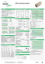
Circuit Diagram (view on relay upper side) - PCB Relay with forcibly guided contacts - Protective separation between control and load curcuit (leakage and creepage distances >8 mm) - EN50205 type A - Double and reinforced insulation between the contacts - Contact Mounting: SIS312 3 NO / 1 NC SIS222 2 NO / 2 NC - Small external dimensions - Nominal coil power 0,33 W - Holding coil power 0,08 W - For railway application (EN50155) on request Basic insulation at 250 VAC Air and creepage distance >4 mm Test voltage 2500 V / 50 Hz / 1 min Double or reinforced insulation at 250 VAC - Air and creepage...
Open the catalog to page 11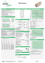
Circuit Diagram (view on relay upper side) - PCB Relay with forcibly guided contacts - Protective separation between control and load curcuit (leakage and creepage distances >8 mm) - EN50205 type A - Double and reinforced insulation between the contacts - Contact mounting: SIS422 4 NO / 2 NC - Small external dimensions - Nominal coil power 0,66 W - Holding coil power 0,20 W - For railway application (EN50155) on request Contact Lifetime for NO Contacts Insulation Data Contact Data Contact material AgCuNi + 0,2 µm Au Type of contact Single contact with notched crown Rated switching capacity 250...
Open the catalog to page 12All ELESTA GmbH catalogs and technical brochures
 SMF5 Series
1 Page
 SMF3 Series
1 Page
 SMD4 Series
1 Page
 SRD SIS3
1 Page
 SRD SIM4
1 Page
 SRD SGR2
1 Page
 SRD SGR2A KV2 PIK
1 Page
 SIP6 Series
1 Page
 SIM4 Series
1 Page
 SIM3 Series
1 Page
 SIM2 Series
1 Page
 SGR282 ZK Series
1 Page
 SIF6 Series
1 Page
 SIF4 Series
1 Page
 SIF3 Series
1 Page
 SIS6 sensitive Series
1 Page
 SIS4 Series
1 Page
 SIS3 Series
1 Page
 SIS2 sensitive Series
1 Page
 SIS2 Series
1 Page
 SISF2 Series
1 Page
 SIR6 sensitive Series
1 Page
 SIR10 Series
1 Page
 SIR8 Series
1 Page
 SID4 Series
1 Page
 SIR 10 Series
1 Page
 SIR 8 Series
1 Page
 SIR 6 sensitive Series
1 Page
 SIR 6 Series
1 Page
 SIR 4 Power Series
1 Page
 SIR 4 sensitive Series
1 Page
 SIR 4 Series
1 Page
 SLR 4 Series
1 Page
 SIM 2 Series
1 Page
 SGR 282 ZK Series
1 Page
 SIF 6 Series
1 Page
 SIF 4 Series
1 Page
 SIF 3 Series
1 Page
 SIS 6 sensitive Series
1 Page
 SIS 6 Series
1 Page
 SIS 4 sensitive Series
1 Page
 SIS 4 Series
1 Page
 SIS 3 Series
1 Page
 SIS 2 sensitive Series
1 Page
 SIS 2 Series
1 Page
 E OI R007 (DSET)
1 Page
 E OI R007 (CSV0)
1 Page


Archived catalogs
 Product Catalogue
36 Pages
 Download Product catalogue 2008
36 Pages


- Switching relay
- Electromechanical relay
- DC electromechanical relay
- Relay module
- Printed circuit board electromechanical relay
- Power relay
- 12VDC electromechanical relay
- 24VDC electromechanical relay
- IEC electromechanical relay
- Plug-in electromechanical relay
- Compact electromechanical relay
- 48VDC electromechanical relay
- DC relay module
- Monostable electromechanical relay
- AC relay module
- 9VDC electromechanical relay
- Relay socket
- 6VDC electromechanical relay
- Electromechanical relay with guided contacts
- 110VDC electromechanical relay