
- Catalogs
- Elektra Elektronik GmbH & Co. Störcontroller KG
- I/O Expansion Modules

I/O Expansion Modules

I/O Expansion Modules
The document provides detailed information on the modular telecontrol system's I/O expansion modules, specifically for the MFW product family. It highlights the expansion capabilities, configuration methods, and technical specifications of various modules.
Functional Description
The expansion modules increase the number of analog and digital I/Os for MFW basic modules. They connect via a CAN bus interface, which also supplies power. Configuration is simplified using DIP switches.
Analog Modules
These modules include both input and output components. The analog input module has 4 inputs with a common GND, switchable between current and voltage. The analog output module provides 4 outputs without needing auxiliary voltage.
Digital Input Modules
Available in standard and pulse-input variants, these modules have 8 configurable inputs. They support binary static and pulse inputs, with options for inverted inputs and operating hour meters.
Relay Output Module
This module consists of 8 relays, configurable as static binary or pulse outputs. The outputs can be adapted for further processing systems via DIP switches.
Transistor Output Module
Featuring 8 transistor outputs, this module is suitable for frequent switching processes. Outputs can be configured as binary static or pulse outputs.
Object Protection Module
Based on digital input module hardware, it includes alarm and inspection functionalities. It provides status updates like "FACILITY ENTERED" and "ALARM" based on input triggers.
Technical Data
The document details operating conditions, power consumption, and electrical specifications for each module type. It includes information on signal voltages, input resistances, and isolation levels.
Order Identification
A list of item numbers and descriptions for various module types is provided, aiding in product selection and ordering.
Dimensional Drawing
Dimensions are provided in millimeters, with a note on the possibility of technical changes.
Catalog excerpts

Modular telecontrol system I/O expansion modules Increasing the number of inputs and outputs of the MFW basic modules › Modular expansion possibilities for any basic module of the MFW product family with digital and analog I/O › Easiest addressing and configuration by DIP switches › 2 CAN bus interfaces per module › Power supply via CAN bus interface › Connection of I/O using plug-in terminals › DIN rail mounting
Open the catalog to page 1
modular telecontrol system Functional description The extension of the amount of analog and digital I/Os of the MFW basic module is possible with the aid of the expansion modules. The connection is done by using the bus cable , which is in the scope of supply on one of the two CAN-bus sockets. The second socket is usable for the connection of another module or for test purposes. The power of the modules is supplied over the CAN-bus. The configuration of the modules is done simply by the DIP switch. Analog modules The analog modules are available as input or output components. Attention: common...
Open the catalog to page 2
Digital inputs Digital input modules are available in two different variants: • Digital input module (Standard) • Pulse-input module (All Inputs are switchable in common between static / pulses) The 8 inputs of the module are configurable per DIP-switch to one of the following input types: Binary input static Except for logged values the actual state of the inputs is acquired and transmitted on every data exchange. To transmit a change of state safely, the state has to line up at least until it is being transmitted. With dial-up systems it means that the state must not change while a transmission...
Open the catalog to page 3
modular telecontrol system Relays output module Relay output modules consist of 8 output relays. These can be used as static binary outputs or pulse outputs. By DIP-switch the outputs A1…A4 can optionally be switched between binary static output or counter value output. In combination with a pulse input module or a master device unit with IEC 60870-5-101/104 interface (output of a pulsed commands) all outputs of the expansion module are configurable as pulsed outputs. The output frequency (pulse width / -pause) is also possible to adapt via DIP-switch to the inputs of a further processing system....
Open the catalog to page 4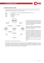
O bject protection module The object-protection module is based on the hardware of a digital input module. Mechanical and electrical data are identically. However the function given in the following is realised. Input 1 … 4 Input 5 Input 6 Input 7 Input 8 E1…E4 optional as binary- or counted measurand (adjustable via DIP-switch ) binary input acknowledgement / inspection alarm input 1 alarm input 2 FACILITY IS UNMANNED Alarm input deactivated Alarm input triggered Acknowledgement activated LEAVING FACILITY Acknowledgement activated FACILITY ENTERED INSPECTION authorised access alarm delay time...
Open the catalog to page 5
modular telecontrol system T echnical data General Data Operating and ambient temperature Air humidity Connection terminals Cross wire section rigid or flexible without wire sleeves with wire sleeves Assembly Housing / protection class Digital input module Power consumption Input variant Signal voltage US Input resistance US Max. counting frequency Min. pulse width / pause Electrical isolation between signal and supply voltage Transistor output module Type of transistor outputs Power consumption Load capacity at transistor outputs Max. count rate Min. pulse width / pause Relay output module Power...
Open the catalog to page 6
i/o expansion modules Produktbezeichnung T echnical data Analog output modules Power consumption Input type Resolution Accuracy Max. burden output current load Minimum impedance of voltage output Object-protection module Power consumption Signal voltage US Input resistance Max. counting frequency Min. pulse width / pause Alarm delay time Alert on-delay time Electrical isolation between signal and supply voltage max. 3,5 W 4 analog outputs (0 ... 10 V or 0 ... 20 mA) 12 Bit less than 0.5 % of final value / 1 year *3 500 Ω 1 kΩ max. 1 W see table see table 5 Hz *1 100 ms *1 0 s ... 4 min (adjustable...
Open the catalog to page 7
Dimensional drawing Dimensions in mm The right to make technical changes is reserved Description 8 DI, signal voltage 12 V 8 DI, signal voltage 24 V 8 DI, signal voltage 60 V 8 DI, signal voltage 110 V 8 DI, signal voltage 220 V 8 DI (static/pulse), signal voltage 24 V 8 Transistor outputs 8 Relay outputs 4 analog outputs 0 ... 20 mA or 0...10 V 4 analog outputs 0 ... 20 mA or 0...10 V Object-protection module, 8 DI, signal voltage 24 V Contact Kontakt Elektra Elektronik GmbH & Co Störcontroller KG | Hummelbühl 7-9 | 71522 Backnang | Germany Tel. +49 (0) 7191.182-0 | Fax. +49 (0) 7191.182-200...
Open the catalog to page 8All Elektra Elektronik GmbH & Co. Störcontroller KG catalogs and technical brochures
 EUW-Series
8 Pages
 Drop-flap Fault Annunciator
8 Pages
 LAB-Series
8 Pages
 Aerials
8 Pages
 Power Supplies
4 Pages
 MSM expansion modules
8 Pages
 Data Transmission System
8 Pages
 Telecontrol on Control Lines
7 Pages
 ZS8A
ZS8A8 Pages


Archived catalogs
 Panel-mounted fault annunciator
16 Pages
- DC power supply
- AC/DC power supply
- Switched-mode power supply
- DIN rail power supply
- Regulated power supply
- DC/DC power supply
- Monitoring relay
- DIN rail monitoring relay
- Multiplexer
- Voltage monitoring relay
- Adjustable monitoring relay
- Three-phase monitoring relay
- Module multiplexer
- Phase monitoring relay
- Phase sequence monitoring relay
- Under-voltage monitoring relay
- Over-voltage monitoring relay
- External power supply
- DC monitoring relay