Catalog excerpts

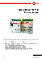
Fault annunciator with internal modem Alarm messaging and controlling via SMS › Alarm and fault messages on mobile phone or fax optional as email or pager › Controlling per SMS for fault annunciators with GSM modem on option › Basic module with 8 digital inputs › Modular fault annunciator expandable to a maximum of 16 digital and 4 analog inputs as well as 8 digital and 4 analog outputs › Up to 4 receivers can be assigned for each message › Internal real time clock, optional external DCF77 receiver › Self monitoring by means of cyclical “alive” messages › Parameterisation per serial interface by means of easy-to-use PC program › Remote parameterisation by SMS or modem dial-up connection
Open the catalog to page 1
fault annunciator with internal modem Functional description The MFW fault annunciator is used for transmitting faults or alarm signals as SMS, fax, pager messages or email to the corresponding terminal equipment. The fault annunciators incorporate an internal modem and are available in 2 principle variants. Variants of the MFW fault annunciator: 1. Basic fault annunciator The basic fault annunciator is designed as a compact unit and provides 8 digital inputs. 2. Modular fault annunciator The basic module has 8 digital inputs. For extending the I/O range, each basic module can be combined...
Open the catalog to page 2
Functional description Acknowledgement function: The fault annunciator can be programmed that on absence of an acknowledgement the alarm message wil be sent again to the same or next respective receiver after a parameterisable delay time. The acknowledgement can be done by a mobile phone simply by using the SMS function "answer" or by modem connection with a PC or on-site with setting the input 8. System time The system time is provided by a built-in battery-backed real time clock that can optionally be maintained by a connectable DCF77 standard time receiver. The regular transmission of an...
Open the catalog to page 3
direct assignment input message SMS, fax, pager not possible Assignation of the messages Type of message Remote parameterisation via SMS Remote parameterisation via modem Acknowledgement function per modem connection not possible yes (Activation of data services for the SIM Card is indispensable) per SMS GSM-Quadband 8 digital inputs not expandable 8 97IAAGAN0BB2 97IIAGAN0BB2 analog / ISDN-EURO-DSS1 8 digital inputs 8DE / 4AE / 8DA / 4AA 20 on connection of each expansion module with 8 DE and 4 AE direct assignment input --> message SMS, fax*, pager not possible yes (Activation of data...
Open the catalog to page 4
Dimensional drawing of the Basis fault annunciator Basic fault annunciator with analog modem Aerial jack Basic fault annunciator with GSM-Modem /t\ Please take into account that modules with internal GSM modem will need determined connection space forthe aerial:
Open the catalog to page 5
FAULT ANNUNCIATOR WITH INTERNAL MODEM Dimensional drawing of the Modular fault annunciator Modular fault annunciator with landline modem Modular fault annunciator with GSM modem /j\ Please take into account that modules with internal GSM modem will need determined connection space forthe aerial: • Aerial "Antennensatze A and GPL" Overall depth 165 mm • Aerial "Antennensatze GB and GBS" Overall depth 180 mm QEB The dimensional drawings of the expansion modules can be taken from the separate data sheet of the
Open the catalog to page 6
Technical Data General data Rated operating voltage Operating voltage range Basic module with expansions Power consumption of basic module Air humidity Connection terminals Wire cross section rigid or flexible without wiresleeve with wiresleeves Assembly Housing / Protection class Basic module with GSM-Modem Operating and ambient temperature Basic module with landline-Modem Operating and ambient temperature Galvanic isolation between dial-up line and supply voltage 24 V DC 10 ... 32 V DC 20 ... 32 V DC approx. 2.5 W maximum 95%, non-condensing pluggable Digital inputs Signal voltage Input...
Open the catalog to page 7
fault annunciator with internal modem Technical data Digital input modules are available with various signal voltages. The corresponding voltage is defined by the 23th digit of the type identification ( e.g. US-GWMOD-G8DEX-DIA-0-BB-0 ). Signal voltage US Voltage key character E F 60 V AC/DC 110 V AC/DC 75 V 130 V Nominal voltage Max input voltage Input voltage DC max Low-state min High-state Input voltage AC max Low-state min High-state Input resistance Subject to technical changes. Order indentification Basic modules Article No. Short description Basic-Fault annunciator / GSM-Modem / 8 DE...
Open the catalog to page 8All Elektra Elektronik GmbH & Co. Störcontroller KG catalogs and technical brochures
-
EUW-Series
8 Pages
-
LAB-Series
8 Pages
-
Aerials
8 Pages
-
I/O Expansion Modules
8 Pages
-
Power Supplies
4 Pages
-
MSM expansion modules
8 Pages
-
Drop-flap Fault Annunciator
8 Pages
-
Data Transmission System
8 Pages
-
Telecontrol on Control Lines
7 Pages
-
ZS8A
8 Pages
Archived catalogs
-
Panel-mounted fault annunciator
16 Pages


