Catalog excerpts

F70 Data transmission system Registration-free, charge-free bi-directional data radio communication within a 70 cm ISM Band Transmitting power 10 mW for transmission ranges up to 2 km Bidirectional communication and flexible system extension up to 31 substations Supply voltage 12 ... 24 V DC Low power version with extremely low power consumption Adjustable radio frequency (64 channels) Most simple parameterisation via DIP switch Radio modules with 4 digital and 2 analog in- and outputs Coupling to control system or PLC via 3964R/RK512 or either Modbus RTU interface at the master station › Plug-in terminals
Open the catalog to page 1
Functional description With the F70 a compact and cost-efficient data transmission system for simple transmission tasks has been created. The radio modules are operated with a transmission power of 10mW, within a 70 cm registration and charge free ISM Band. The F70 is designed for the bidirectional transmission of measured values, count pulses, digital signals, status information, analog nominal values and commands. Depending on the model of the central station it can communicate with up to 31 substations. For each device of the basic module, 4 digital and 2 analog inputs and outputs are...
Open the catalog to page 2
DATa transmission system Functional description Because of the limited number of galvanic I/O’s at the master station ( 4 digital and 2 analog in- and outputs ) only a maximum of 4 substations are operational by use of the galvanical I/O’s. Thus at the substations is only a part of the available in- and outputs is indeed useable, however the datas can be exchanged by easy methods in the master station without use of the serial interface. In the following table the number and arrangement of the I/O’s of the substations depending on the number of substations used, is represented. with three...
Open the catalog to page 3
Variants The modules are available in two versions – basic and low-power. The basic version (F70-32) can be parameterised via DIP switch for operation as master station or substation. The low-power substation (F70-UL4) is only useable as substation and has an integrated energy management system to ensure extremely low energy consumption. Device type Item number Device type I/O Protocol interface 3964R/RK512 *2 Self-monitoring LED + relay contact Internal real-time clock yes no Connection for external DCF77 receiver Configuration via DIP General settings switch - Radio frequency (64...
Open the catalog to page 4
DATA TRANSMISSION SYSTEM Given a supply of energy, the basic version can be used. All components stay constantly activated. Since the modem is also always switched on, the substation can be constantly contacted by the central station and/or data can be The Low Power substation version F70-UL4 was developed for use with battery and solar systems and can only be used as a substation. To reduce energy requirements, this module version can alternate between two operating modes at parameterisable times: Energy saving mode In this operating mode all modules not absolutely needed (e.g. modem) are...
Open the catalog to page 5
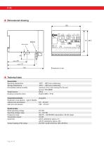
Dimensional drawing aerial socket laloge analoge UB/DC Funk Technical data General data Operating temperature Storage temperature Permissible relative humidity Weight approx. Housing / protection class maximum 75 % in the average for the year Connection terminals Conductor cross-section - without wire-end sleeves with wire-end sleeves Electrical data Rated operating voltage Operating voltage range Frequency range Transmission power Cycle time Contact loading of the relays with 4 substations approx. 5 s with 31 substations approx. 40 s
Open the catalog to page 6
DATa transmission system T echnical data Digital inputs Input voltage Rated voltage Maximum voltage Voltage for high-state Voltage for low-state Input resistance Response delay Maximum count rate (E1) 24 V DC 48 V DC > 9,0 V DC < 2,2 V DC 18 kΩ approx. 50 ms 10 Hz (only in the basic version) F70-32 (basic version) Power consumption Digital outputs Load capacity of the output transistors Total current Pulse width / pause (A1) Analog inputs Measuring range Resolution Accuracy Load current input 0 ... 20 mA 10 Bit Fault < 1 % of final value 100 Ω Analog outputs Measuring range Resolution...
Open the catalog to page 7
DATa transmission system A pplication examples • Sewage treatment (e.g. sludge level measurement and scraper bridges) • Control and monitoring of rakes in intake basins • Recording of levels for weir systems • Storm overflow reservoirs, pumping stations, elevated tanks, wells, inspection chambers • Coal excavators in open-cast mining • Mobile measuring units (e.g. locks, waterways, buoys) • Monitoring of systems in industry and traffic engineering • Monitoring and control for facility management Order identification Data transmission devices Article no. Short description: Basic-variant for...
Open the catalog to page 8All Elektra Elektronik GmbH & Co. Störcontroller KG catalogs and technical brochures
-
EUW-Series
8 Pages
-
LAB-Series
8 Pages
-
Aerials
8 Pages
-
I/O Expansion Modules
8 Pages
-
Power Supplies
4 Pages
-
MSM expansion modules
8 Pages
-
Drop-flap Fault Annunciator
8 Pages
-
Telecontrol on Control Lines
7 Pages
-
ZS8A
8 Pages
Archived catalogs
-
Panel-mounted fault annunciator
16 Pages


