Catalog excerpts

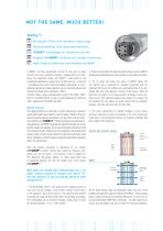
No liquids! Filled with harmless neutral gas. Stacked windings with optimized geometry. SINECUT™ technology for maximum current. Original CAPAGRIP™ terminal for reliable connection. High safety by advanced self-healing and BAM™. In MKPg™, we have concentrated the best of tong years of know how and first-class production facilities, combined with eco-friendliness and operational safety. The MKPg™ is well-suited for aft conventional applications in power factor correction and can - if required - be adapted to your most critical and toughest requirements. It is protected by enhanced self-healing dielectric and an irreversible overpressure disconnector (break-action mechanism, ..BAM"). Technical layout, testing and application accord to IEC 60831, UL810, CSA 22.2 and G0ST1282-88, as welt as Indian Standards IS 13340 and 1 3341. Approved by CSA (C/US) and GOST. Special Features: The winding elements are immersed in neutral insulation gas instead of liquids which would cause trouble in case of leakage. Thanks to the use of special metallizing patterns.devetoped in our own state of the art metallizing facilities, our SINECUT™ slitting technology and optimized winding geometries, our MKPg™ capacitors distinguish themselves not only by high AC-voitage toad capacity, but also by outstanding suitability for high rms and surge currents. Unlike some of our competitors who proudly quote fantasy ratings, we have severely tested our capacitors beyond their rated values, allowing for sufficient margin and guaranteeing flawless operation within the specifications. Safe and reliable connection is guaranteed by our original CAPAGRIP™ terminal. Having been copied by numerous competitors alt over the world, it has become a kind of standard for PFC capacitors. Be warned, however, of cheap copies which may be appearing identical, but tack the reliable grip of the original CAPAGRIP ™. What makes our stacked short winding design such a far better technical solution for standard and special PFC than the concentric or slim tall windings offered by other manufacturers? 1. The big diameter offers a very targe area for charging currents to cross over into the winding, in other words: reduced current stress at the capacitor's most critical spot (i.e. the sensitive bond between contacting zinc spray and film at both ends of the winding). On average, the corresponding area of concentric windings is three times, of slim/ tail stacked windings 1.3 to 1.5 times smaller. 2. Thanks to short height and enhanced metal coating structures, MKPg™ windings have substantially less series resistance, and produce less tosses. 3. The six targe and strong zinc layers of MKPg™ (where the zinc particle size is optimised for excellent connection with the metallised film) serve for multiple and uninterrupted drain of the dissipated heat from the capacitors' hotspot to the surface, white the (just) two zinc layers on the tong concentric windings are even sectioned by the PET insulation between their phases. On stacked, but tail windings, the zinc layers are rather distant from the windings' hotspots, and offer only smalt area for heat drain. 4. The entire construction of stacked windings is more robust, electrical connection as welt as insulation is far more reliable and stable than in the complicated structure of concentric windings with their sensitive PET separations. Alt the above features help to dramatically reduce the risk of field problems and premature capacitor failures. The MKPg is - by its principal design, superior know-how and matching dimensions, as welt as by its careful workmanship (100% Made in Germany) - the ideal capacitor not only for your new projects, but also as retrofit for existing installations.
Open the catalog to page 1
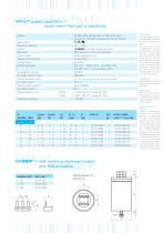
Maximum RMS Current Rating lmax Maximum rms value of permissible current in continuous operation. In accordance with EN 60831 all ELECTRONICON capacitors are rated at least 1.3xIn, allowing for the current rise from permissible voltage and capacitance tolerances as well as harmonic distortion. Continuous currents that exceed these values will lead to a buildup of heat in the capacitor and - as a result - reduced lifetime or premature failure. Permanent excess current may even result in failure of the capacitor's safety mechanisms, i. e. bursting or fire. CAPAGRIP™ L with matching discharge...
Open the catalog to page 2All ELECTRONICON Kondensatoren catalogs and technical brochures
-
Capacitors for power electronics
35 Pages
-
PEC Application notes
52 Pages
-
E62-3PH AC FILTER
24 Pages
-
E62 AC/DC
40 Pages
-
E51 AC/DC
24 Pages
-
E63 DC
16 Pages
-
E61 DC
34 Pages
-
E56 DC / E59 AC/DC
32 Pages
-
E50.U SR17
3 Pages
-
FKD-MV™
16 Pages
-
E90 MSD™
32 Pages
-
280 MKP UHD
2 Pages
-
275 MKPg Heavy Duty 400-440V
2 Pages
-
FK-DR CU/ALU
8 Pages
-
ELR™ Line Reactors
1 Pages
Archived catalogs
-
ELR Line Reactors (English)
1 Pages
-
E93 DSC data chart (English)
2 Pages
-
E61 Catalogue
6 Pages
-
E51 E53 E55 Catalogue
16 Pages
-
Power Factor Controller
5 Pages
-
Discharge Reactor ELDr
1 Pages
-
Detuned Reactors FKDr
16 Pages


