
- Catalogs
- Electromen
- EM-67

EM-67

EM-67
- Direction change capability
- Braking functionality
- Continuous or 2-step speed control
- Adjustable acceleration and braking ramp
- Adjustable current limit and load compensation
- Compensation for supply voltage variations
- High efficiency with a self-recovery fuse
- Rail mountable design
- Supply Voltage: 20-34 Vdc
- Idle Current: Approx. 40mA
- Control Voltage: 0-5V / 0-10V
- Control Current: 3A rms / 5A momentary
- Control Power: 70W rms
- Braking Power: 30W (1/10 duty cycle)
- Voltage Loss: 1V at Im=3A
- Current Limit: 0.2-5A
- Fuse: 3A self-recovery
- Ramp Time: 0.5-10s
- Control Potentiometer: 1-10kohm
- Digital Control: "On" at Uin=4-30V, "Off" at Uin=0-1V or open
- EMC Testing: EN 50081-2 & 50082-2
- Dimensions: 65x72x30mm
- Weight: Approx. 70g
- P1 Ramp: Set acceleration and braking ramp (0.5-10s).
- P2 Speed Set for Speed2: Adjust speed2 preset value (0-100%).
- P3 Current Limit: Set maximum motor current (0.2-5A), indicated by a red light.
- P4 Control Range: Set desired control range (0-5V to 0-50V).
- P5 Load Compensation (RI): Compensate load effects on motor speed, starting from minimum.
Catalog excerpts
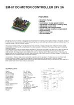
EM-67 DC-MOTOR CONTROLLER 24V 3A FEATURES: • Direction change • Braking • Continuous / 2-step speed control • Adjustable acceleration / braking ramp • Adjustable current limit • Adjustable load compensation • Supply voltage variation compensated • High efficiency • Self recovery fuse • Rail mountable EM-67 DC-motor controller is designed for 24V permanent magnet motors with brushes in the power range of 5-70W (0,2-3A). Due to advanced PWM-controlling the unit runs with high efficiency and low thermal loss. The braking energy is fed to a power resistor. The output voltage of the unit is regulated so that changes in supply voltage won’t affect the motor speed. Additionally the unit has RI-compensation, that can be used to minimize motor speed changes in changing loading situations. The required amount of RI-compensation depends on the motor used and is set with a trim. With this feature, a good motor speed versus control voltage ratio can be reached. Speed adjustment can be made with potentiometer or voltage signal. Alternatively the unit can also be used in two speed mode. In this case the speeds are set with trimmers on the card, and activation is done with switch or control voltage. The unit gives additional 10V for potentiometer and control switches. Acceleration / braking ramp can be adjusted depending on the situation, this feature gives controlled and smooth direction change. Direction change can be controlled with either switch or control voltage. The psupply inputos protected against overcurrent and reversed polarity using a self recovery fuse. EM-67 is EMC-tested and meets heavy industry standards. TECHNICAL DATA: Supply Idle current Control voltage Control current Control power Braking power Voltage loss Current limit Fuse Ramp Control potentiometer Digital control EMC-testing Dimensions Weight POWER REGUL. POWER CONTROL LOGIC VOLTAGE MEAS. IR-COMP. I-LIM. CURRENT MEAS.
Open the catalog to page 1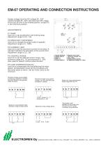
EM-67 OPERATING AND CONNECTION INSTRUCTIONS 65 mm Supply voltage must be DC-voltage 20...34V (recommended 26...32V) with less than 20% ripple. At first set all trims to the middle position, except P5 in the minimum position. P1 RAMP Use trim to set acceleration and braking ramp. Adjustment range is 0.5...10s. P2 SPEED SET FOR SPEED2 Use trim to change the preset value of speed2. Adjustment range is 0...100%. P3 CURRENT LIMIT Use trim to set the maximum current of the motor. A red light indicates the activation of the current limit. Adjustment range is 0.2...5A P4 CONTROL RANGE Use trim to set...
Open the catalog to page 2All Electromen catalogs and technical brochures
 ELECTROMEN STOCK PRODUCTS
157 Pages
 EM-324
2 Pages
 EM-M69
1 Page
 EM-115
2 Pages
 EM-180
2 Pages
 EM-M17Bf/HZ converter
1 Page
 EM-M41I/A/mA converter
1 Page
 EM-M22I/A/mA converter
1 Page
 EM-M11AI/A/mA converter
1 Page
 EM-165Positioning controller
2 Pages
 EM-217BAC motor controller
2 Pages
 EM-285DC motor controller
2 Pages
 EM-76DC motor controller
1 Page
 EM-231DC motor controller
3 Pages
 EM-213DC motor controller
2 Pages
 EM-12ADC motor controller
2 Pages
 EM-101DC motor controller
3 Pages


- Acceleration sensor
- Triaxial acceleration sensor
- Signal conditioner
- Stepper motor controller
- MEMS accelerometer
- Remote control receiver
- Signal converter
- Speed controller
- Wireless receiver
- Radio remote control receiver
- DIN rail signal conditioner
- Digital motor controller
- Digital receiver
- DC speed controller
- Bluetooth receiver
- Current signal isolator
- Phase angle controller
- Brushless speed controller
- Power regulator