Catalog excerpts

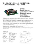
EM-136 STEPPER MOTOR MICROSTEPPING CONTROLLER UNIT 12-45V 0.5-4A FEATURES: • Bipolar chopper • Wide supply voltage range • Full-, half-, quarter-, and 1/8-step operation • 8-programmable phase currents • Auxiliary oscillator • Acceleration- and braking ramp • Self recovery fuse • Very high efficiency • Low heat dissipation • Rail mounting base available EM-136 is bipolar-chopper type stepper motor controller. Bipolar operation suits most stepper motors and provides the best torque. The microstepping feature gives high performance also at low rpm. The power stage is mosfet-type so it runs with very high efficiency. There are four stepping modes: full, half, quarter and 1/8. Desired mode is set with two control inputs. The phase current ( current limit ) can be set in eight different levels using dip-switches. A wide phase current set range makes it possible to use the device with several different motors. The controller features an auxiliary oscillator, which has 7 preprogrammed frequencies. The frequency is set with three control inputs. Auxililary oscillator in EM-136 has also an acceleration ramp feature, which can be used to change frequencies flexibly, so that the motor will start up reliably even at high frequencies. The acceleration ramp time is set with a trim. The inputs operate with so called positive logic, in other words the inputs are activated with connecting the input to positive voltage. The inputs also work with TTL-logic level control. The power state of EM-136 has self recovery fuse that protects the controller from over current and reversed input voltage polarity. EM-136 BLOCK DIAGRAM TECHNICAL DATA: 4A PTC FUSE Operating voltage Idle current Current set Voltage loss Fuse Aux. osc. freq. Ramp speed Aux. freq. precision Digital control Step freq. Operating temp. Dimensions Weight 12-45Vdc approx. 25mA (enable "0") 0.5; 1,0; 1.5; 2.0; 2.5; 3.0; 3,5 and 4.0A 1V when Im=1A 4A self recovery. 200, 500, 1000, 2000 Hz 3000, 5000, 8000 Hz 0,2...3s (0...8000 Hz) better than 0,5% "on" when Uin 4 -30V "off" when Uin 0-1V max. 15 kHz 0-50°C 87x73x35mm approx. 90g 5V + 7 SUPPLY 8 1 REGULATION ENABLE SUPPLY INPUT - SELECT 2 STEP MODE 11 STEP MODE 12 3 STEPPING LOGIC 10 DIRECTION A 9 STEPPING 4 POWER STAGE SM 5 CURRENT SET B 6 13 AUX. OSCILLATOR 14 15 ACCELERATION RAMP PHASE CURRENT
Open the catalog to page 1
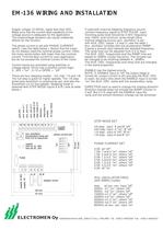
EM-136 WIRING AND INSTALLATION Supply voltage 12-45Vdc, ripple less than 20% Make sure that the current feed capability of the voltage source is adequate for the application. The undervoltage situation can cause undesired effects for the function. The phase current is set with PHASE CURRENT switch ( see the table below ). Notice that the motor do not always need the nominal phase current. Often the motor works better with lower than the nominal current. Find the best current for your application, but do not exceed the nominal current of the motor. Control inputs are activated using switches...
Open the catalog to page 2All Electromen catalogs and technical brochures
-
ELECTROMEN STOCK PRODUCTS
157 Pages
-
EM-324
2 Pages
-
EM-67
2 Pages
-
EM-M69
1 Pages
-
EM-115
2 Pages
-
EM-180
2 Pages
-
EM-82Transducer / Vibration
1 Pages
-
EM-M17Bf/HZ converter
1 Pages
-
EM-M41I/A/mA converter
1 Pages
-
EM-M22I/A/mA converter
1 Pages
-
EM-M11AI/A/mA converter
1 Pages
-
EM-165Positioning controller
2 Pages
-
EM-217BAC motor controller
2 Pages
-
EM-162AC motor controller
1 Pages
-
EM-285DC motor controller
2 Pages
-
EM-76DC motor controller
1 Pages
-
EM-231DC motor controller
3 Pages
-
EM-213DC motor controller
2 Pages
-
EM-12ADC motor controller
2 Pages
-
EM-101DC motor controller
3 Pages


