Catalog excerpts

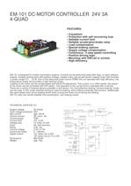
EM-101 DC-MOTOR CONTROLLER 24V 3A 4-QUAD FEATURES: • 4-quadrant • Protection with self recovering fuse • Settable current limit • Settable acceleration/brake ramp • Load compensation • Special braking options • Supply voltage compensation • Continuous / 2-step speed controlling • Positive driving logic • Mounting with DIN-rail or screws • High efficiency EM-101 is designed for modern automation systems. Controls can be performed easily with relay- or open collectoroutputs. Analog controls work with positive voltage. Usable motor can be permanent magnet motor with brushes in power range of 5 ... 70 W. Due to the advanced pulse control (PWM) the unit operates with high efficiency, low temperature losses and provides a high starting torque. Loading of the motor can be compensated with inbuilt RI-adjustment. The current, or in other words, the torque of the motor can be controlled with DIP-switch. The operation of the current limit is indicated with a red led. There are a variety of braking options available in this device. For most effective braking “reverse braking”-mode can be used. In this mode reversed driving is used for braking, which effects extremely fast function. Additionally the card utilises short circuit braking which short circuits the motor circuit during the braking. EM-101 also has inbuild settable time acceleration- and braking ramps. EM-101 BLOCK DIAGRAM TECHNICAL DATA EM-101 Supply voltage Over voltage protection Idle current Control current Control power Current limit Voltage loss Fuse Ramp Control voltage Control pot.meter Digital control Dimensions Weight 20-34Vdc 36V app. 50mA 3A, mom. 4A 70W 0,2...4.2A 1V when Im=3A 3A, self recovery 0,5s...5s 0-5V, 0-10V 2...10kohm “on” when Uin 4-30V “off” when Uin=0-1V or NC 89x73x26 app. 70g 10 10V 5mA 5 CONTROL VOLTAGE POWER REGUL. 3A PTC FUSE + CONTROL GND 1 SUPPLY IN 2 7 6 FORWARD or REVERSE REVERSE RUN SPEED SET 3 - SPEED SCALE OR SPEED-1 CONTROL LOGIC POWER STAGE H-BRIDGE + RUN SPEED-1 4 8 9 RUN SPEED-2 VOLTAGE MEAS. SPEED-2 RAMP. CURRENT MEAS. I-LIM. REVERSE BRAKE TIME IR-KOMP. Rbs Rk MOTOR
Open the catalog to page 1
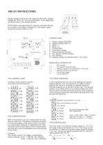
EM-101 INSTRUCTIONS Supply voltage must be DC with ripple less than 20%. Supply voltage 20...34V ( 26...32V recommended ). In the beginning set all trimmers in the middle position. 1 2 3 4 - + + NOTE! When reversed braking is used the controller will take a very high current peak. Capacitor for the power supply should be at least 4700uF at 1A. MOTOR Cr POWER SOURCE 89 mm CONNECTORS: P2 ON OFF ON 1 2 3 4 CURRENT LIMIT 1 SPEED 2 2 3 OFF RAMP COMPENSATION Rk P1 66 mm 73 mm Rbs SPEED-1 / POT. RANGE FUSE T3A 1. Supply voltage 20-34Vdc 2. Supply voltage GND 0V 3. Motor (-) 4. Motor (+) 5. Control...
Open the catalog to page 2
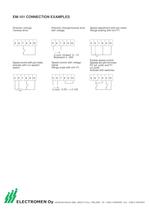
EM-101 CONNECTION EXAMPLES Direction change /reverse drive. 5 6 7 8 9 10 Direction change/reverse drive with voltage. 5 6 7 8 9 10 Speed adjustment with pot.meter. Range scaling with trim P1. 5 6 7 8 9 10 U-cont. forward 0...1V Backward 4...30V Speed control with pot.meter, activate with run speed1switch. 5 6 7 8 9 10 Speed control with voltage signal. Range scale with trim P1. 5 6 7 8 9 10 Double speed control. Speeds set with trimmers P2 (s2, pin9) and P1 (s1,pin6) Activate with switches. 5 6 7 8 9 10 U-cont. 0-5V --> 0-10V ELECTROMEN Oy Vähäheikkiläntie 56B, 20810 Turku, FINLAND Tel....
Open the catalog to page 3All Electromen catalogs and technical brochures
-
ELECTROMEN STOCK PRODUCTS
157 Pages
-
EM-324
2 Pages
-
EM-67
2 Pages
-
EM-M69
1 Pages
-
EM-115
2 Pages
-
EM-180
2 Pages
-
EM-82Transducer / Vibration
1 Pages
-
EM-M17Bf/HZ converter
1 Pages
-
EM-M41I/A/mA converter
1 Pages
-
EM-M22I/A/mA converter
1 Pages
-
EM-M11AI/A/mA converter
1 Pages
-
EM-165Positioning controller
2 Pages
-
EM-217BAC motor controller
2 Pages
-
EM-162AC motor controller
1 Pages
-
EM-285DC motor controller
2 Pages
-
EM-76DC motor controller
1 Pages
-
EM-231DC motor controller
3 Pages
-
EM-213DC motor controller
2 Pages
-
EM-12ADC motor controller
2 Pages


