MS320
1 /2Pages
MS320
1 /2Pages
Catalog excerpts

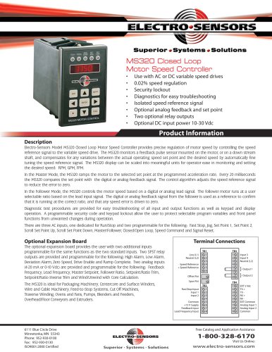
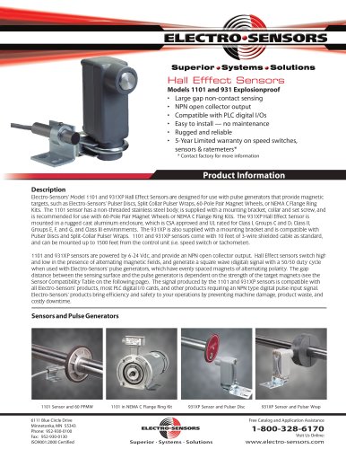
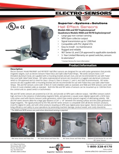
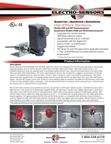
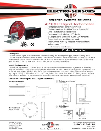
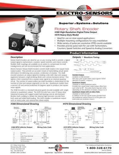
Superior * Systems * Solutions Motor Speed Controller Use with AC or DC variable speed drives Security lockout Diagnostics for easy troubleshooting Isolated speed reference signal Optional analog feedback and set point Two optional relay outputs Optional DC input power 10-30 Vdc Product Information Electro-Sensors Model MS320 Closed Loop Motor Speed Controller provides precise regulation of motor speed by controlling the speed reference signal to the variable speed drive. The MS320 monitors a feedback pulse sensor mounted on the motor, or on a down stream shaft, and compensates for any variations between the actual operating speed set point and the desired speed by automatically fine tuning the speed reference signal. The MS320 display can be scaled into meaningful units for operator ease in monitoring and setting In the Master Mode, the MS320 ramps the motor to the selected set point at the programmed acceleration rate. Every 20 milliseconds the MS320 compares the set point with the digital or analog feedback signal. The control algorithm adjusts the speed reference signal to reduce the error to zero. In the Follower Mode, the MS320 controls the motor speed based on a digital or analog lead signal. The follower motor runs at a user selectable ratio based on the lead input signal. The digital or analog feedback signal from the follower is used as a reference to confirm that it is running at the correct ratio, and that any speed error is driven to zero. Diagnostic test procedures are provided for easy troubleshooting of all input and output functions as well as keypad and display operation. A programmable security code and keypad lockout allow the user to protect selectable program variables and front panel functions from unwanted changes during operation. There are three AC inputs, one dedicated for Run/Stop and two programmable for the following: Fast Stop, Jog, Set Point 1, Set Point 2, Scroll Set Point Up, Scroll Set Point Down, Master/Follower, Closed/Open Loop, Speed Command and Signal Reset. Optional Expansion Board The optional expansion board provides the user with two additional inputs programmable for the same functions as the two standard inputs. Two SPST relay outputs are provided and programmable for the following: High Alarm, Low Alarm, Deviation Alarm, Zero Speed, Drive Enable and Ramp Complete. Two analog inputs (4-20 mA or 0-10 Vdc) are provided and programmable for the following: Feedback Frequency, Lead Frequency, Master Setpoint, Follower Ratio, Setpoint/Ratio Trim, Setpoint/Ratio Inverse Trim and Wind/Unwind with Core Calculation. The MS320 is ideal for Packaging Machinery, Centercore and Surface Winders, Wire and Cable Machinery, Feed-to-Stop Systems, Cut Off Machines, Traverse Winding, Ovens and Fans, Pumps, Blenders and Feeders, Overhead/Floor Conveyors and Extruders. Terminal Connections - Speed Reference Run/Stop Input Feedback Input Lead Frequency Input 6111 Blue Circle Drive Superior ■ Systems ■ Solutions Free Catalog and Application Assistance
Open the catalog to page 1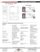
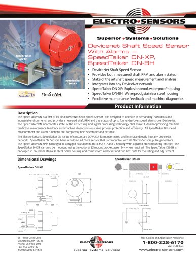
MS320 Motor Speed Controller Dimensional Drawings • MS320 (Dimensions In Inches) System Diagram Specifications • MS320 Closed Loop Motor Speed Controller Input Power Voltage . . . . . . . . . . . . . . . . . . . . . . . . . 115 Vac Standard 230 Vac Optional 50 - 60 Hz, 6W 10 - 30 Vdc Optional Fuse . . . . . . . . . . . . . . . . . . . . . . . . . . . . External Fuse required, 1/16 slo-blo recommended for 115 Vac and 1/32 A for 230 Vac, 2 Amp 10 - 30 Vdc Sensor Supply . . . . . . . . . . . . . . . . . . . 12 Vdc unreg., 100 mA max. Sensor Input . . . . . . . . . . . . . . . . . . . . Square, Triangle,...
Open the catalog to page 2All Electro-Sensors catalogs and technical brochures
 HazardProTm
12 Pages
 Brochure ELECTRO SENSORS
40 Pages
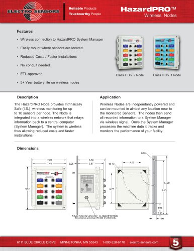 HAZARDPRO™ NODE
2 Pages
 HAZARDPRO™ BEARING SENSOR
2 Pages
 VTHP
VTHP2 Pages
 DIGITAL RING KITS
3 Pages
 Accu-Tach & Accu-Dial
2 Pages
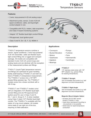 TT420-LT
2 Pages
 TT420
TT4202 Pages
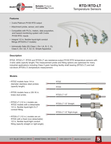 RTD/RTD-LT
2 Pages
 PM500
PM5002 Pages
 SCP1000 / SCP2000
2 Pages
 HH100 Hand-Held Tachometer
2 Pages
 TR400
TR4002 Pages
 TR5000
2 Pages
 SG1000A
2 Pages
 SG1000B
2 Pages
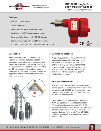 SG1000C
2 Pages
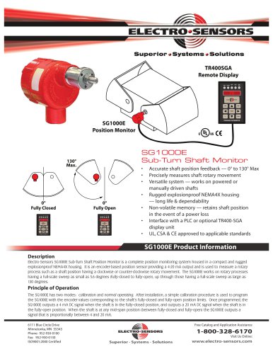 SG1000E
2 Pages
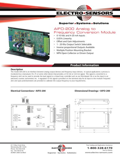 AIFO-200
2 Pages
 MTS Series & SCU-200
2 Pages
 VS1/ VS2
2 Pages
 VUM800
2 Pages
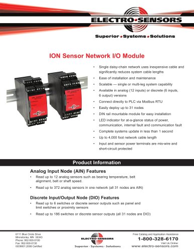 ION Remote I/O
2 Pages
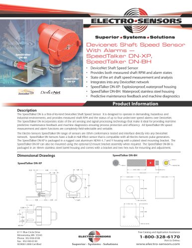 SpeedTalker-DN(BH) DeviceNet
2 Pages
 SpeedTalker-DN(UI)
2 Pages
 MS196
MS1962 Pages
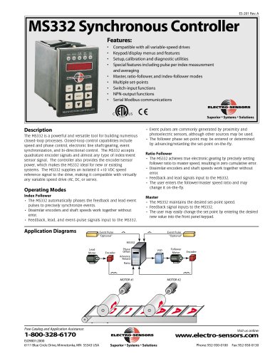 MS332
MS3322 Pages
 SpeedTalker-DN(XP) DeviceNet
2 Pages
 SA420
SA4202 Pages
 LRB1000 / LRB2000
2 Pages
 Stainless Steel Disc Guards
2 Pages
 Shaft Speed Switch
12 Pages
 Product Brochure
28 Pages
 ST420 Shaft Tachometer
2 Pages
 Sensors - 907 XP Hall-effect
2 Pages
 Sensors - 1101 Hall-effect
2 Pages
 Sensors - 608-1 Proximity Sensor
2 Pages
 Sensors - 906 Hall-effect
2 Pages
 TT-420 Temperature Transmitters
2 Pages
 Tachometers - HH100
2 Pages
 Sensors - 906 Hall Effect
2 Pages
 Electro-Sentry™
4 Pages
 Tachometers - AP1000
2 Pages
 SpeedTalker DN-BH
2 Pages
 Signal Conditioners - SA420
2 Pages
 Vibration Monitors - VS-1
2 Pages
 Speed Switches - SS110
2 Pages


- Temperature probe
- Angular encoder
- Resistance temperature sensor
- Incremental encoder
- Proximity switch
- Incremental rotary encoder
- Cylindrical proximity sensor
- Pt100 temperature transducer
- Solid-shaft rotary encoder
- Stainless steel temperature transducer
- Hollow-shaft rotary encoder
- Magnetic rotary encoder
- Industrial rotary encoder
- Safety electric switch
- Rotary electric switch
- RTD temperature sensor
- DIN rail converter
- Threaded temperature sensor
- Analog indicator
- Potentiometer