


SOLID-STATE RELAYS

SOLID-STATE RELAYS
- Solid-State Relays: The catalogue categorizes SSRs into zero-crossing relays, instant commutation relays, and D.C. commutation relays, each suited for specific load types such as resistive, capacitive, or inductive loads.
- General Features: All relays include a snubber filter for voltage spike protection. Additional protection with a varistor and fast-reacting fuses is recommended in industrial environments.
- EC Reference Standards: The relays comply with the Low Voltage Directive (2014/35/EU) and the Electromagnetic Compatibility Directive (2014/30/EU).
- Advantages: Benefits include low power supply, high reliability, reduced response time, no mechanical wear, compatibility with digital circuits, and noiseless operation.
- Limitations: Limitations include voltage drop, output limited to A.C. or D.C., frequent need for a dissipator, and sensitivity to transient voltages.
- Installation Guidelines: Relays should be installed in well-ventilated areas to ensure proper heat dissipation and should not be stacked to avoid overheating.
- Product Range: Lists various series of SSRs, including SCR, MOSFET, IGBT, and phase angle control relays, each with specific models and technical specifications.
- Accessories: Accessories such as metal oxide varistors and heat sinks are available to complement the relays.
- Repetitive Surge Peak: On-state current ranges from 400 A to 1000 A with a critical rise of off-state voltage at 500 V/μS.
- Output Voltage Drop: Consistently at 1.8 V across models.
- Off-State Leakage Current: Varies from 3 mA to 15 mA.
- Minimum Working Current: Ranges from 80 mA to 200 mA.
- Input Voltage: Ranges from 3-32 VDC to 90-240 VAC/DC.
- Control Current Range: Varies from 3-32 mA to 5-15 mA.
- Control Pick-Up Voltage: Ranges from 3 V to 90 V.
- Control Drop-Out Voltage: Ranges from 1 V to 60 V.
- Maximum Closing Delay: For zero crossing commutation is 1/2 cycle or 20 ms.
- Maximum Opening Delay: For zero crossing-instant commutation is 1/2 cycle or 30 ms.
- Isolation Voltage: Consistently at 4000 V.
- Operating Temperature: -20/+80 °C.
- Storage Temperature: -40/100 °C.
- SSR08 Series: Includes models with output currents ranging from 10 A to 125 A, with various input and output voltage specifications.
- Zero Crossing Commutation: Available for models with output currents from 10 A to 125 A.
- Phase Angle Control Relays: Models SSR08-25240I, SSR08-40240I, and SSR08-50240I with input control of 4-20 mA.
- UL and CE Certification: Ensures compliance with safety and performance standards.
- Metal Oxide Varistors (MOV) and Heat Sinks: Available for enhancing relay performance.
- Control Voltage: 3.5-32 VDC for SSR08D models, 12-32 VDC for SSR08D-251200A.
- Output Voltage: Ranges from 3 to 200 VDC for SSR08D models, and 5 to 1200 VDC for SSR08D-251200A.
- Output Current: Up to 40A for SSR08D models, and 25A for SSR08D-251200A.
- Isolation Voltage: 2500V for SSR08D models, 4000V for general specifications.
- Operating Temperature: -20/+80°C for SSR08D models, -30/+80°C for SSR01/02/05 models.
- Storage Temperature: -40/100°C for all models.
- VDE and CE certifications for SSR08D models.
- UL-CSA certification for SSR01/02/05 models.
- Metal Oxide Varistors (MOV) and heat sinks are available as accessories.
- Input-Output Insulation: 3,750 V for input-output insulation.
- Operating Temperature: -30°C to +80°C for all models.
- Storage Temperature: -40°C to +100°C.
- Isolation Voltage: Up to 4000V for certain models.
- SSR870/871/88D-360 Series: Features zero crossing and instant commutation types, with output currents of 3A to 5A and input voltages ranging from 3-32 VDC.
- SSR91 Series: Designed for DC load commutation with a nominal load voltage of 60 VDC and features such as high reliability and high switching frequency.
- SSR20/21 Series: Offers zero crossing commutation for AC models and instantaneous commutation for DC models, with output voltages from 12 to 275 VAC or 0 to 35 VDC.
- Low control current and high input-output insulation.
- RC filter protection for AC models.
- VDE and CE certifications for compliance with EC standards.
- Critical Rate of Rise of Off-State Voltage: 400V/µS
- Output Voltage Drop: 1.2V
- Off-State Leakage Current: 1mA
- Minimum Working Current: 50mA
- Dimensions: Provided in mm
- Input/Output Isolation: 2500V
- Output Voltage Range: 12 to 275 VAC or 0 to 35V DC
- Nominal Voltage: 24V DC
- Load Voltage Range: 0-35VDC
- Output Current: 4A
- Non-Repetitive Surge Peak Current: 40A at 10ms
- Operating Temperature: -20 to +80°C
- Storage Temperature: -40 to +100°C
- Non-polarized input
- LED indicators for input and output voltage
- Timed output options: 4A-24VDC or 3A-240 VAC
- Multi-function timing with four functions and time scales from 0.1s to 6h
- Zero crossing commutation for AC models
- RC filter protection for AC models
- DIN rail mounting and 20 pole comb for parallel connection of SSRs
- SDT-0424B: 24VAC/DC input, 4A output current
- SAT-03240B: 24VAC/DC input, 3A output current
- SDE-50048A: 10-40 VDC input, 500mA output current
- SSR15-25240A: 4-32 VDC input, 25A output current
- SSR07 Series: Various models with output currents of 25A and 40A, and input voltages ranging from 3-32 VDC to 200-265 VAC
- Conforms to EC standards
- UL-CSA certifications available for certain models
- SC3-08D Series: Designed for three-phase applications with a nominal voltage of 480 VAC and an output current of 3 A. It supports both zero crossing and instant commutation. The input voltage range is 6-32 VDC, with a peak voltage of 800 VAC and input-output insulation of 4000 V.
- SC3-12D Series: Offers a range of models with output currents from 10A to 90A and supports both DC (4-32 VDC) and AC (90-280 VAC) control voltages. The load voltage range is 50-480 VAC, with peak voltages between 800 and 1200 V.
- SM3 Series: Features models with output currents up to 5A and supports both zero crossing and instant commutation. The load voltage range is 20-510 VAC, with a peak voltage of 1200 V and input-output insulation of 5000 V.
- Input/Output Data: Includes control voltage ranges, control current ranges, pick-up and drop-out voltages, and input resistance for various models.
- Thermal Data: Operating temperatures range from -30°C to +80°C, with storage temperatures from -40°C to +100°C.
- LED indicators for input voltage and auxiliary contact signaling.
- Built-in varistor protection and non-polarized input for certain models.
- Mechanical auxiliary contacts available for specific models.
The document outlines the specifications for solid-state relays (SSR) with an output voltage range of 12-275VAC and a repetitive peak off-state voltage of 600VAC. The output current is rated at 5A at 50°C, with a non-repetitive surge peak on-state current of 300A for 10ms. The I²t rating for fuse choice is 450A²S for 10ms. The critical rate of rise of off-state voltage is 1000V/µS, and the on-state output voltage drop is between 0.85V and 1.5V at 25°C with 5A/90mA. The off-state leakage current is 4mA, and the minimum working current is 90mA.
Standards and Accessories:
The relays conform to EC reference standards. Accessories include metal oxide varistors (MOV) and heat sinks. The relays are compact, DIN rail mountable, and feature universal input voltage ranges of 20-75VDC and 20-240VAC. They include an input voltage LED, zero crossing or instantaneous commutation, and a protected output with RC filter and varistor. The input-output insulation is rated at 2500V.
Technical Data:
The maximum closing delay for zero crossing commutation is 1/2 cycle, and for instant commutation, it is 10ms. The maximum opening delay for zero crossing-instantaneous commutation is 1/2 cycle. The operating temperature range is -20°C to +70°C, and the storage temperature range is -40°C to +100°C.
Installation and Protection:
When installing multiple SSRs side by side, a derating of output current should be considered. For heat sink installation, thermal grease should be used, and relays should be spaced apart to facilitate air flow. To protect SSRs from short circuits or overloads, ultrarapid fuses should be used, with the I²t value of the fuse being lower than that of the SSR. Varistors are recommended to protect against voltage spikes, with a response time between 20 and 50 ns.
Heat Sink Calculation:
The document provides a formula for calculating the appropriate heat sink for a solid-state relay based on current and ambient temperature. The formula considers the joint temperature of the semiconductor, ambient temperature, dissipated power, and thermal resistances between various components.
- Input Voltage: Ranges from 3-32VDC and 90-280VAC for various models.
- Operating Temperature: -30 to +80°C, with storage temperature ranging from -30 to +100°C.
- Control Current Range: 8-30 mA for DC and 4-20 mA for AC inputs.
Input/Output Technical Data:
- Turn-on Time: Maximum of 10ms for DC and 40ms for AC.
- Turn-off Time: Maximum of 10ms for DC and 80ms for AC.
- Insulation Voltage: 4000V between input and output.
Output Technical Data:
- Nominal Voltage: 240VAC and 600VAC options available.
- Output Current: Rated at 25A and 40A, with forced cooling for higher current.
- On-state Voltage Drop: 1.6VAC for 240VAC models and 1.8VAC for 600VAC models.
- Off-state Leakage Current: 5 mA for all models.
- Frequency Range: 47-63 Hz.
Design and Features:
- Solid-state relays with zero crossing or random switching.
- LED status indication and IP20 protection.
- DIN rail and back plate mountable with built-in snubber.
- CE certification and RoHS compliance.
Wiring and Connection Specifications:
- Input and output connections support various wire types and gauges, with specified tightening torques.
- Isolation voltage for input-output is 4000V, and terminal to case is 2500V.
Thermal Data:
- Operating temperature ranges from -40 to +80°C, with storage up to 130°C.
- Derating curves provided for high-temperature applications.
Accessories:
- Includes metal oxide varistors (MOV) and heat sinks.
General Information:
- EL.CO. S.r.l. reserves the right to make changes without notice.
- All parameters measured at Ta=25°C.
- Dimensions: Various models with dimensions ranging from 45x128x110 mm to 93x182.5x143 mm.
- Input Technical Data: Control voltage ranges from 5-24 V DC or 24-230 V AC/DC, with maximum control voltage up to 32 VDC or 253 V AC/DC. Response time is up to 1 cycle.
- Output Technical Data: Operational current varies by model, with maximums of 10A to 125A. Rated operational voltage up to 600VAC-50/60 Hz.
- Thermal Data: Operating temperature range is -5 to 60°C, with storage temperature from -20 to 80°C. Cooling is by natural convection.
- IP20 protection rating.
- Built-in varistor and RC filter protection.
- Zero crossing commutation to reduce network disturbances.
- Thermal overload protection via optional thermostats (TO6290).
The document specifies that the SPC 1 is compliant with IEC 60947-4-3 / EN 60947-4-3 standards for AC semiconductor contactors for non-motor loads. In burst firing control mode, no action is necessary. In phase angle control mode, if the current (I) is less than 10A, no action is needed as the internal filter suffices. However, if I is greater than 10A, a 1uF capacitor should be connected between N/L and L1.
Two application scenarios are described: 1) A thermostat is connected in series with the control supply of the controller. If the heatsink temperature exceeds 90°C/100°C, the control supply is switched off, and it is switched on again when the temperature drops to approximately 70°C. 2) The thermostat is connected to a PLC or another controller for controlled shutdown in case of overheating.
The document provides detailed specifications for various solid-state relays (SSR) and semiconductor motor controllers. It includes information on line voltage, control voltage, motor load capacity, and dimensions. The SSRSMC3-DOL series is designed for accurate control of three-phase motors in applications requiring frequent starts and stops. The SSRSRC3 series is designed for reversing the direction of three-phase motors.
Input and output technical data are provided, including control voltage range, operational current, leakage current, and response time. The document also specifies the thermal data, such as operating and storage temperatures, and cooling methods.
The document outlines overload protection methods and mentions compliance with EC reference standards and approvals like CAN/CSA-C22.2 and UL Std No.508. It also highlights the importance of thermal overload protection using thermostats.
The document emphasizes that the products are designed for class A equipment and may cause radio interference in domestic environments, requiring additional mitigation methods. It also notes that EL.CO. S.r.l reserves the right to make changes without notice.
- By Circuit Breaker: A correctly installed and adjusted overload relay in a 3-phase motor prevents total short circuits to earth or between phases. The winding limits the short circuit current to trigger the circuit breaker without damaging semiconductors. The magnetic trip response current is approximately 11 times the maximum adjustable current.
- By Fuses: The document specifies maximum I²t values for fuses used with SSR models, ensuring protection against short circuits.
- Operational Current: Models are available with operational currents of 15A or 25A.
- Temperature Ratings: The document provides derating guidelines for high-temperature applications.
- Protection Standards: The products conform to EC standards and are CE marked.
The document outlines the specifications for the SSRSMC3/32...3/15 series AC semiconductor soft starters. These devices are designed to control the acceleration and deceleration of three-phase motors. The ramp-up and ramp-down times are adjustable from 0.5 to 10 seconds, and the initial torque can be adjusted from 0 to 85% of the nominal start torque, with an optional kick-start function.
Procedures:
The document provides detailed procedures for adjusting the ramp-up and ramp-down times, as well as the initial torque settings. It emphasizes the importance of setting these parameters correctly to ensure optimal motor performance and avoid mechanical surges.
Standards and Approvals:
The soft starters comply with the EN60947-4-2 standard and are CE marked. They are designed for class A equipment, and additional mitigation methods may be required in domestic environments to prevent radio interference.
Recommendations:
Users are advised to ensure that the trimmers are not set in intermediate positions to avoid corrupting the time and torque adjustments. The document also recommends using a manual thermal magnetic circuit breaker for overload protection, in accordance with EN 60204-1.
Technical Data:
The document includes detailed input and output technical data, such as control voltage range, operational current, and response time. It also provides information on the dimensions for DIN rail mounting and the cooling method.
Application Hints:
Examples of applications with the soft starter are provided, including line-controlled and input-controlled soft-start, as well as combining reversing electronic contactors with the soft starter for motor reversing applications.
Key Data from Tables:
The selection table provides information on line voltage, control voltage, and motor size compatibility for different models. The document also includes data on short-circuit protection using circuit breakers and fuses, with specific values for maximum I²t of the fuses.
This document is a technical guide on solid-state relays, focusing on thermal overload protection, functional diagrams, and the adjustment of time and torque settings for soft starters. It includes detailed instructions on wiring configurations, protection mechanisms, and application examples for motors.
Thermal Overload Protection
Thermal overload protection is achieved by inserting a thermostat into the designated slot on the right side of the static group. The system accepts two types of thermostats: TO6290. This protection ensures that the motor does not overheat by tripping the relay when necessary.
Functional Diagrams and Wiring
The document provides diagrams for standard and inside-delta wiring configurations for connecting soft starters to three-phase motors. It explains the importance of correct wiring to ensure proper motor function and protection.
Adjusting Time and Torque
Instructions are provided for adjusting the ramp-up time and initial torque using trimmers. It is crucial not to set the rotary switches between positions to avoid corrupting the pre-set time and torque adjustments. The soft starter reads these settings when in the off state.
Soft Starter Applications
Several application examples are provided, including line-controlled and input-controlled soft starts, as well as combining reversing electronic and mechanical contactors with soft starters. These examples illustrate how to achieve soft starting and stopping of motors, including reversing direction for motors up to and exceeding 4 kW.
Short-Circuit and Overload Protection
The document outlines methods for short-circuit protection using circuit breakers and fuses, specifying the maximum I²t values for different models. Overload protection is achieved by installing a manual thermal magnetic circuit breaker, which acts as a circuit isolator according to EN 60204-1 standards.
Recommendations
Ensure that trimmers are not set in intermediate positions to maintain accurate time and torque settings. Allow a delay of approximately 0.5 seconds between forward and reverse control signals to prevent voltage spikes when the motor stops.
Conclusion
This guide provides comprehensive instructions for setting up and protecting motors using solid-state relays and soft starters. It emphasizes the importance of correct settings and configurations to ensure efficient and safe motor operation.
- Modular Power Controller Models: Various models are available with output currents of 10A, 25A, and 50A, and output voltages ranging from 48 to 450V AC.
- Technical Data: Includes dual LED displays, universal inputs for thermocouples and thermoresistances, and accuracy of ±0.5% span ±1 digit.
- Power Supply: Options include 24V AC/DC or 100-240V AC.
- Communication: RS485 serial port with MODBUS-RTU protocol.
- Control: Programmable PID or ON/OFF control with autotuning and self-tuning algorithms.
- Alarms: Configurable alarms for no load or load in short conditions.
- Outputs: Up to 4 outputs, including programmable options for digital input or logic output.
- Wiring Diagrams: Detailed diagrams for connecting multiple modules and configuring auxiliary outputs.
- Connections: 24 screw terminals for various connections, including power and communication.
- Programming Key: KEYA01 for programming the controller via PC or USB to RS485 conversion.
- Flat Cable: Used for connecting modular power controllers, available in different lengths.
- Mounting: DIN rail mounting is supported.
- Protection: IP20 protection degree, with integrated fuse for output protection (except for 50A models).
- Conformity: Complies with low voltage and electromagnetic compatibility directives.
Catalog excerpts

1 - RELE ALLO STATO SOLIDO 1 - SOLID-STATE RELAYS La produzione base dei rele allo stato solido EL.CO. si divide in tre gruppi principali: 1. Rele a commutazione zero (zero crossing) I rele a commutazione di zero innescano quando la tensione di uscita passa in prossimita dello zero e disinnescano sempre a corrente zero. Sono particolarmente indicati alla commutazione di carichi resistivi o capacitativi. 2. Rele a commutazione istantanea I rele a commutazione istantanea innescano simultaneamente al segnale di ingresso e quindi in ogni punto della curva sinusoidale della tensione di uscita e disinnescano sempre a corrente zero. Sono particolarmente indicati alla commutazione di carichi induttivi. 3. Rele per commutazione in D.C. I rele per commutazione di carichi in corrente continua innescano e disinnescano simultaneamente alla tensione di controllo. Applicazioni consigliate: I rele allo stato solido trovano particolare applicazione dove e richiesta una elevata frequenza di commutazione unita anche alla possibilita di commutare, mediante tensioni di controllo limitate (3V-3mA), correnti elevate (90 A-480V) con un isolamento di 4KV tra ingresso e uscita. Presentano inoltre una totale tollerabilita alle vibrazioni, all'ossidazione, agli urti meccanici e non danno origine ne ad archi ne a rimbalzi. The EL.CO. standard production of the solid state relays is divided into three main groups. 1. Zero-crossing relays The zero crossing relays pick-up when the output voltage is near to zero and always drop-out at zero-current. They are particularly suitable for the commutation of resistive and capacitive loads. 2. Instant commutation relays The instant commutation relays pick-up simultaneously to the input signal and then at each point of the sinusoidal output voltage curve and drop-out at zero-current. They are particularly suitable for the commutation of inductive loads. 3. D.C. commutation relays The relays for D.C. load commutation pick-up and drop-out simultaneously to the control voltage. Recommended application: The solid-state relays can particularly be used where a high commutation frequency is required together with the possibility of commutating, by means of limited control voltage (3 V-3 mA), high currents (90 A-480V) with 4 KV insulation between input-output. They are extremely resistant to vibrations or oxidation as well as to mechanical impacts and do not cause arcs nor fluctuations. CARATTERISTICHE GENERALI - GENERAL FEATURES Tutti i rele sono provvisti di filtro snubber che li protegge da eventuali inneschi indesiderati causati da una velocita di crescita della tensione in uscita troppo elevata; tuttavia in talune applicazioni il dispositivo non risulta protetto a causa di elevati spike di tensione presenti talvolta negli ambienti industriali. Al dispositivo in questi casi deve essere applicato un varistore in parallelo all'uscita, in modo da proteggerlo dai sopracitati spike. Per proteggere invece i dispositivi da sovracorrenti e bene installare per ogni fase un fusibile extra rapido e non un normale fusibile che interverrebbe a dispositivo gia danneggiato. NORMATIVE CE DI RIFERIMENTO: Direttiva 2014/35/EU, direttiva Bassa tensione (BT) Direttiva 2014/30/EU, direttiva compatibility elettromagnetica (EMC) All the solid state relays are provided with a snubber filter, which protects them from any undesirable spikes caused by an excessive speed of the output voltage. However, in certain applications, it has been found that the device is still not protected, as a result of the elevated voltage spikes which may sometimes be present in industrial environments. In such cases, a varistor must be applied to the device, in parallel with at the output, so as to protect the device from the above said spikes. To protect the devices from overcurrents, it is recommended that a fast-reacting fuse be installed for each phase, rather than a normal fuse which would only intervenes once the device has already been damaged. EC REFERENCE STANDARDS: Low Voltage Directive (LVD) 2014/35/EU Electromagnetic Compatibility (EMC) Directive 2014/30/EU Catalogo generate Genera/ catalogue EL.CO. S.r.l si riserva di apportare modifiche senza alcun preavviso. - EL.CO. S.r.l. Reserves the right to make changes without obligation of notice.
Open the catalog to page 1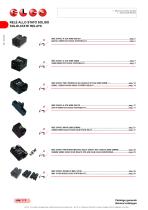
1 - RELÈ ALLO STATO SOLIDO 1 - SOLID-STATE RELAYS RELÈ ALLO STATO SOLIDO SOLID-STATE RELAYS Catalogo generale General catalogue EL.CO. S.r.l si riserva di apportare modifiche senza alcun preavviso. - EL.CO. S.r.l. Reserves the right to make changes without obligation of n
Open the catalog to page 2
1 - RELÈ ALLO STATO SOLIDO 1 - SOLID-STATE RELAYS Catalogo generale General catalogue EL.CO. S.r.l si riserva di apportare modifiche senza alcun preavviso. - EL.CO. S.r.l. Reserves the right to make changes without obligation of no
Open the catalog to page 3
1 - RELÈ ALLO STATO SOLIDO 1 - SOLID-STATE RELAYS Catalogo generale General catalogue EL.CO. S.r.l si riserva di apportare modifiche senza alcun preavviso. - EL.CO. S.r.l. Reserves the right to make changes without obligation of n
Open the catalog to page 4
1 - RELÈ ALLO STATO SOLIDO 1 - SOLID-STATE RELAYS Catalogo generale General catalogue EL.CO. S.r.l si riserva di apportare modifiche senza alcun preavviso. - EL.CO. S.r.l. Reserves the right to make changes without obligation of notice.
Open the catalog to page 5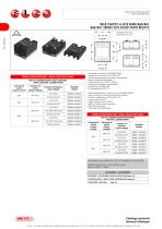
1 - RELE ALLO STATO SOLIDO 1 - SOLID-STATE RELAYS RELE STATIC! A SCR SERIE 860/861 860/861 SERIES SCR SOLID STATE RELAYS Dimensioni in mm. Dimension in mm. TABELLA SELEZIONE RELE' - RELAY SELECTION TABLE * Corrente nominale 10/25/40/70/90A * Tensione di uscita da 20 a 530 VAC * Commutazione zero crossing o istantanea * Bassa corrente pilotaggio * Tensione di picco fino a 1200 V * Isolamento ingresso uscite 4000 V * Protezione con filtro RC * Omologazioni VDE -CE * Rated operational current up to I0/25140170190A * Zero crossing or instantaneus commutation * Output voltage from 20 to 530 VAC *...
Open the catalog to page 6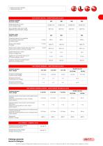
1 - RELE ALLO STATO SOLIDO 1 - SOLID-STATE RELAYS Catalogo generate General catalogue EL.CO. S.r.l si riserva di apportare modifiche senza alcun preavviso. - EL.CO. S.r.l. Reserves the right to make changes without obligation of notice.
Open the catalog to page 7All EL.CO. catalogs and technical brochures
 MOTOR CONTROL EMS24 Series
2 Pages
 SSR RANGE
2 Pages
 PRODUCT RANGE
2 Pages
 PRODUCT RANGE
124 Pages
 TEMPERATURE CONTROLLERS
56 Pages
 RELAY INTERFACE MODULES
33 Pages
 POWER SUPPLIES
31 Pages
 SOLID STATE RELAYS
122 Pages
 Power Supplies
34 Pages
 RELAY INTERFACE MODULES
28 Pages
 Temperature Trasmitters
40 Pages
 TEMPERATURE CONTROLLERS
44 Pages
 TIMERS AND MODULAR PROTECTION
27 Pages
 DIGITAL POWER FACTOR CONTROLLERS
15 Pages
 SSRSTL3 series
2 Pages
 SSRSMC series
2 Pages
 MPCD
MPCD5 Pages
 MPC
MPC5 Pages
 SM3 SERIES
2 Pages
 3 PHASE SOLID STATE RELAYS
2 Pages
 SDP, SAP series
3 Pages
 sd/sa
sd/sa2 Pages
 ERIES SCR SOLID STATE RELAYS
3 Pages
 GENSET ACCESSORIES
4 Pages
 TEMPERATURE TRANSMITTERS
54 Pages
 POWER SUPPLY
27 Pages


- DC power supply
- AC/DC power supply
- Digital temperature control
- Switching relay
- Communication gateway
- Temperature controller
- Fieldbus gateway
- Ethernet gateway
- Electromechanical relay
- DIN rail power supply
- Digital temperature controller
- Serial gateway
- DC electromechanical relay
- Time relay
- DIN rail gateway
- Automation temperature controller
- PID temperature control
- PID temperature controller