
- Catalogs
- EKOMAT GmbH & Co. KG
- EKOMAT Flow divider designs


EKOMAT Flow divider designs

EKOMAT Flow divider designs
- Synchronised Running: Flow dividers ensure the synchronized operation of multiple motors or cylinders from a single pump by dividing the total pump flow into partial flows, preventing sequential operation based on pressure requirements.
- Pressure Multipliers: They can function as pressure multipliers, efficiently increasing output pressure. The EKO.MTO range supports pressures up to 280 bar, with special versions for higher pressures.
- Lubricating-Oil Flow Divider: Ensures equal distribution of lubricating oil to multiple friction bearings, maintaining synchronized flow across sections.
- Internal Pressure Drop: Radial-piston flow dividers experience larger pressure drops compared to gear motor designs, varying with outlet pressure and model configurations.
- Overcoming Pressure Drop: High pressure is often needed in one flow direction. Flow dividers can be installed in return lines or bypassed during high-pressure phases using check valves.
- Synchronisation Differences: Factors affecting synchronization include oil viscosity, temperature, pressure load variability, and system pressure levels. Synchronization tolerances vary by model and size.
- Using a "Driver": An additional section can increase outlet pressures, useful in applications like lifting platforms.
- Compensating Synchronisation Errors: Corrections occur as cylinders reach the end of their stroke. Pressure relief valves and minimum pressure feeds are essential for maintaining synchronization.
- Hydraulic Fluids: Designed for use with mineral oil, with operating temperatures from -25°C to +80°C. Other fluids like HFC and HFD are also compatible.
- Flow Divider Start-Up: Small flow dividers may not start under high outlet pressure. Check valves can relieve pressure and facilitate start-up.
- Various series and sizes are available, including EKO.MKA, EKO.MTO, EKO.HTO, and EKO.MT-GM, each with specific applications and configurations.
- Noise Levels: Gear-motor flow dividers can cause noise levels over 1800 rpm, which may be unacceptable. Displacement should be chosen accordingly.
- Synchronization Ratios: Typically 1:1, but different ratios can be requested. Contact Jahns technical staff for assistance.
- Application Limits: Flow dividers may leak oil, necessitating pilot-operated non-return valves between the flow divider and cylinder. They cannot compensate for errors due to differential oil compression at varying load pressures.
- Inlet/Outlet Blocks: Available for EKO.MTZ, EKO.MT, and EKO.MTL flow dividers. Must be ordered with the flow dividers as later assembly is problematic.
- Pressure Control Valves: Set by measuring the distance 'L' using a caliper rule. Tables provide pressure levels and corresponding spring lengths.
- Installation Instructions: Flow dividers should be fitted close to cylinders with equal length pipe connections. Use mineral oil as per DIN 51524 with recommended viscosity between 12 and 100 cSt.
- Commissioning: Radial piston flow dividers require filling with oil before commissioning to prevent running dry.
- Filtration: Critical for high synchronization levels. Recommended nominal filter rating of 10 µm and absolute value of 25 µm.
- Temperature Range: Operating temperature is -25°C to +80°C with normal seals and up to +100°C with Viton seals.
- Pressure and Length Correlation: Tables provide pressure values for different spring colors and lengths.
- Flow Divider Specifications: Various sizes and displacements are listed with corresponding flow rates and pressure limits.
- Flow dividers should be installed as close to the cylinders as possible with equal length pipe connections.
- Gear flow dividers do not require a leakage oil connection and do not need to be filled with oil before commissioning.
- Radial piston flow dividers have specific leakage oil connection requirements.
- Examples provided for ordering flow-divider valves with specific configurations and pressure settings.
- Models: EKO.MTO and EKO.HTO series, with different sizes and configurations.
- Displacement per Section: Ranges from 24.9 cm³/U to 149.7 cm³/U depending on the model.
- Flow Rates: Minimum flow per section ranges from 12 l/min to 80 l/min, and maximum flow ranges from 66 l/min to 220 l/min.
- Pressure Ratings: Continuous pressure ranges from 235 bar to 320 bar, with peak pressures up to 380 bar.
- Materials: Cast iron housing is used for durability.
- Input and Output: Various threaded and SAE connections are specified for input and output ports, including G1/2", G3/4", and SAE NW32.
- Measuring Ports: G1/4" measuring ports are available for each section.
- Tank and Low-Pressure Feeding: Connections are provided for tank and low-pressure feeding, typically G1/2" or G1 1/4".
- Order codes specify the number of sections, displacement per section, and additional features such as threaded connections and design series.
- Examples include EKO.MTO-4-55-EA7 and EKO.HTO-4-35-FI.
- Restrictions apply when using fluids other than mineral oil, with specific pressure and temperature limits for HFC water glycol and HFD phosphate esther.
- Weight varies by model and configuration, ranging from 2.1 kg/section to 75 kg/section.
- Dimensions are provided for calculating total length based on the number of sections used.
- All models conform to DIN ISO 1219 standards for hydraulic circuit diagrams.
- Models and Capacities: The document lists several models such as EKO.MT-GM1, EKO.MT-GM2, EKO.MTL, and EKO.STL, each with different displacement capacities ranging from 100 cm³/rev to 3000 cm³/rev and flow rates from 28 l/min to 550 l/min.
- Pressure Ratings: Continuous pressure is rated at 240 bar, with intermittent pressure up to 300 bar across all models.
- Power Ratings: Maximum power per section varies from 14 kW to 120 kW depending on the model.
- Input and Output Ports: Various connection types are specified, including SAE and G-threaded connections, with specific instructions for connecting input and output ports together.
- Drain Ports: All models include drain ports with a maximum pressure of 2 bar or 10 bar, depending on the model, and must be connected to the tank.
- Measuring Ports: Each section includes measuring ports for monitoring purposes.
- Order codes are provided for each model, indicating specific configurations such as threaded connections, inlet and outlet blocks, and the number of sections.
- Complete drawings for different sizes and configurations are available upon request.
- Instructions are provided for calculating the total length of flow dividers based on the number of sections, with specific measurements for each section type.
- Feet placement guidelines are included for stability during installation.
Catalog excerpts
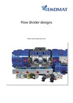
Flow divider designs
Open the catalog to page 1
© Ekato GmbH & Co. KG 2014 Bei Produktverbesserungen behalten wir uns technische und optische Veränderungen vor. Alle Angaben wurden sorgfältig erstellt und überprüft. Trotzdem können wir für unvollständige oder fehlerhafte Angaben keine Haftung übernehmen. Nachdruck, auch auszugsweise, nur mit unserer Genehmigung.
Open the catalog to page 2
Flow-divider application Synchronised running Pressure multipliers If several motors or cylinders are operate from a single pump without any means of controlling their individual flows only the motor or cylinder with the lowest pressure requirement would start its work cycle. The motor or cylinder with the next lowest pressure requirement would only start when the first unit has completed its work cycle. This mode of operation is generally undesirable and it is therefore necessary for the total pump flow to be divided into a series of partia flows.This can be achieved in the following ways: As mentioned...
Open the catalog to page 3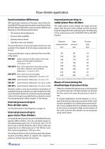
Required Input Pressure output pressure pressure drop Synchronisation differences With particular reference to the gear-motor flow dividers EKO.MTO but also for the radial-motor flow dividers EKO.MT-GM and EKO.MTL synchronisation differences depend on the following parameters: • Oil viscosity and temperature • Pressure load varability • System pressure levels • Total flow rate to be divided Precise indications of synchronisation levels are only possible if the details of all the above parameters are known. A general indication may be obtained from the following values: EKO.MK under...
Open the catalog to page 4
Flow-divider application Using a “driver” This is achieved by adding an extra section of equal or greater displacement to the flow divider.The return line of this section is connected directly to tank so that it in effect works as a motor for the other sections in the flow divider thereby increasing their outlet pressures. This is useful, for example, in lifting platforms that should lower under action of their own weight, but where the weight of the empty platform is insufficient for this to occur. Compensating synchronisation errors - installation of the flow divider in the hydraulic circuit As...
Open the catalog to page 5
Flow-divider application Hydraulic fluids Application limits Our flow dividers are designed to be used with mineral oil in accordance with DIN 51524. The operating temperature range is fixed at -25°C to +80°C with normal seals and -25°C to +100°C when using Viton seals. Due to the propensity of all flow dividers to leak oil it is not possible to keep the cylinders under pressure for an extended period of time. As a consequence it is necessary to fit pilot-operated non-return valves in every line between flow divider and cylinder. The recommended oil viscosity is between 12 and 100 cSt, while at start-up...
Open the catalog to page 6
The pressure control valves are set to these values The fact that the pressure valves are counter-sunk means that it is not possible to adjust them,whilst at the same time looking at the pressure manometer.In order to set the valves it is necessary to remove the pressure cartridge from the block. Since the safety valves need not be set to a great degree of precision and can easily accommodate a tolerance of 3 bar, it is possible to set the valve by simply measuring the distance 'L' using a calliper rule. In the diagrams (left) you can read off the values for pressure = f(L) for the different...
Open the catalog to page 7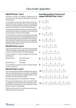
Flow-divider application EKO.MTO Sizes 1 and 2 Aluminium housing. The different displacements of units within the same size are indicated by the width of the housing. It is possible to interconnect flow dividers of any displacement listed in the tables. The same is also possible in terms of combining both component groups. This is important when they are used as pressure boosters. The inlets to the individual chambers are interconnected internally. The number of connections on the inlet side must be based on the flow to be divided. In version‘A’each section has a combined pressure relief and suction...
Open the catalog to page 8
Integral pressure valves in the MTO General points Flow dividers must be fitted as close to the cylinders as possible and the pipe connections to the individual chambers must be of equal length, as far as this is possible. Hydraulic fluids, viscosities Oil flow dividers are designed for use of mineral oil in accordance with DIN 51524. The recommended oil viscosity is between 12 and 100 cSt, while at start-up they are approved for maximum values up to 600 cSt. chambers of the divider. Leakage oil pressure maximum of 10 bar, or a maximum of 1.5 bar for versions with protruding measurement shaft. Commissioning...
Open the catalog to page 9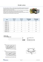
The valve produces 2 flows or riunifies 2 flows. The total flow should lie between the minimum and maximum limits below. Within the flow-limits, the flow are nearly independant of oil-pressure and viscosity. Using this valve it's important to know that a stop of the first flow causes a throttling of the second-one. This produces heat. Please take care of this fact. Generally we recommead the alloy-version, last not least due to the lower costs. Only a pressure of over 210 bar leads to the steel-version. 24 max. total flow (l/min) EKO.MKA Flow-divider valve in alloy EKO.MKS Flow-divider...
Open the catalog to page 10
www.ekomat.de- Seite 11 - -^EKDMAT
Open the catalog to page 11
Displacement min. flow max. flow Continue per section per section per section pressure Peak pressure (bar) max. pressure difference between the sections outputs (bar) Providing that the flow-noise is not an issue, it is possible to increase the pressure values in the chambers. Example: EKO.MTO-4-5-AVR 4-section flow-divider with all section of 5,5 cm3/rev, pressure valve adjustable AVR Pressure control valves adjustable from 130 to 280 bar, standard Spring colour red, preset to approx. 180 bar AVG Pressure control valves adjustable from 90 to 200 bar, Spring colour green,...
Open the catalog to page 12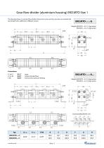
The drawing shows a 4-section flow-divider. Using more or less sections, you have to calculate the total length with a difference of B each section.
Open the catalog to page 13All EKOMAT GmbH & Co. KG catalogs and technical brochures
 CETOP control valves
1 Page
 COMPACT UNITS
1 Page
 AS A SYSTEM SOLUTION
1 Page
 Ekomat WE4-10
10 Pages
 Ekomat WE3-06
10 Pages
 Ekomat WE3-04
8 Pages
 Directional Control Valves
8 Pages
 Gear Flow Divider
12 Pages
 Radialpiston Flowdivider
24 Pages
 Product Overview
12 Pages


- Electrically operated valve
- Gas solenoid valve
- Level limit switch
- Direct-operated solenoid valve
- Liquid level detector
- Pressure switch
- Hydraulic valve
- Mechanical pressure switch
- Float level switch
- IP65 solenoid valve
- Pack unit
- Electric hydraulic power unit
- Adjustable pressure switch
- Flange valve
- ISO solenoid valve
- Compact hydraulic power unit
- Electronic pressure switch
- Control solenoid valve