
- Catalogs
- EKOMAT GmbH & Co. KG
- Directional Control Valves


Directional Control Valves

Directional Control Valves
Catalog excerpts

Directional Control Valves Solenoid Operated 4/3-, 4/2- way directional control valves with solenoid control Solenoids can be turned around their axis to any position Push button manual override Installation dimensions acording to DIN 24 340 / ISO 4401 / CETOP RP121-H Subplates see data sheet HA 0002 Functional Description The RPE3-04 directional control valves consist of cast WE3-04 iron housing (1), control spool (5) with two centering springs (4) and operating solenoids (2, 3). The three-position directional valves are fitted with two solenoids and two springs. Two-position directional valves have either one solenoid and one return spring or two solenoids and a detent assembly. The operating solenoids are DC solenoids supplied through connectors A, B (6, 7). For AC supply the solenoids are provided with a rectifiers which are integrated in the DIN connector socket as part of the solenoid. By loosening the nut (8), the solenoid can be turned around its axis up to 360°. In the case of solenoid malfunction or power failure, the spool of the valve can be repositioned by manual override (9), provided the pressure in the T-port does not exceed 363 PSI (25 bar). The valve housing (1) is phosphate coated and the solenoids (2, 3) are zinc coated.
Open the catalog to page 1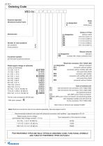
Ordering Code_ Solenoid Operated Directional Control Valve Nominal size Number of valve positions three positions Functional symbols see the table functional symbols Rated supply voltage of solenoids The AC coils correspond with E5 type. without orifice Manual override N2 covered with rubber protective boot no designation without connector K1 connector without rectifier K2 connector without rectifier with LED K3 connector with rectifier K4 connector with rectifier with LED K5 connector without rectifier Type of solenoid coil E1 with terminal for the connector, EN 1745301-803 E2 with terminal...
Open the catalog to page 2
Technical Data Valve size Maximum flow Maximum operating pressure at ports P, A, B Maximum operating pressure at port T Pressure drop Hydraulic fluid Fluid temperature range (NBR / Viton) Phosphate ester fluids (HFD-R) Viscosity range Maximum degree of fluid contamination Maximum allowable voltage variation Maximum switching frequency Switching time, ON; at v = 156 SUS (32 mrrf/s) Switching time, OFF; at v = 156 SUS (32 mrrT/s) Duty cycle Service life Weight - valve with 1 solenoid - valve with 2 solenoid Mounting position Spool Symbols
Open the catalog to page 3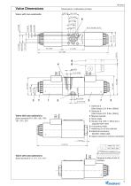
Valve Dimensions Dimensions in millimeters (inches) 18.5(0.728) Valve with two solenoids 1 Solenoid a [(Nut torque 2.21 ft-lbs. (3Nm)] 2 Solenoid b [(Nut torque 2.21 ft-lbs. (3Nm)] 3 Manual override 4 Name plate 5 Square ring 7.65 x 1.68 (4 pcs.) supplied with valve 6 4 mounting holes 7 Retaining nut of the solenoid 8 Electrical connector, DIN EN1745301-803 9 Space required to remove connector Valve with one solenoid a Spool symbols R11, R21, A51, P51, Y51, C51, Z51 Valve with one solenoid b Spool symbols Z11, X11, C11, H11 Required surface finish of interface
Open the catalog to page 5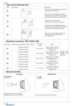
Type of the Solenoid Coil Dimensions Solenoid coil with terminal for the electrical connector, EN 1745301-803 Solenoid coil with terminal for AMP-Junior-Timer electrical connector. Solenoid coil with integrated quenching diode (bipolar transil diode) and terminal for the electrical connector, EN 1745301-803 Solenoid coil with integrated quenching diode (bipolar transil diode) and terminal for AMP-Junior-Timer electrical connector. Solenoid coil with integrated rectifier and terminal for the electrical connector, EN 1745301-803 Electrical connector, EN1745301-803 Description Description (see page...
Open the catalog to page 6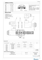
Orifice in P-Port Type Seal ring P-port orifices limits the flow into the directional control valve. Attention: When the orifice in P port is additionally mounted the standard used square ring NBR is replaced with O-ring from Viton. Solenoid coil Retaining nut with seal Electrical connector Orifice in P-port with seal Seal kit Mounting bolts Solenoid retaining nut with seal Type of the nut Standard nut Nut with rubber boot Ordering number 15874500 15874800 * CSA Upon request
Open the catalog to page 7
HA 4014 Electrical connector, EN 175301-803 Connector A grey Type designation Ordering number Dimensions, number Square ring O-ring 7.65 x 1.68 (4 pcs.) 16 x 2 (2 pcs.) 7.65 x 1.78 (4 pcs.) 16 x 2 (2 pcs.) Standard NBR70 Viton Mounting bolts Dimensions, number M5 x 35 DIN 912-10.9 (4 pcs.) Caution! When the distributor contains two electromagnets any of the two electromagnets can be switched on only after the other one switches off. The electromagnets switching time on distributors with locking arrangement must not be shorter than 60 ms. Distributors with other interconnections than those shown...
Open the catalog to page 8All EKOMAT GmbH & Co. KG catalogs and technical brochures
 CETOP control valves
1 Page
 COMPACT UNITS
1 Page
 AS A SYSTEM SOLUTION
1 Page
 EKOMAT Flow divider designs
38 Pages
 Ekomat WE4-10
10 Pages
 Ekomat WE3-06
10 Pages
 Ekomat WE3-04
8 Pages
 Gear Flow Divider
12 Pages
 Radialpiston Flowdivider
24 Pages
 Product Overview
12 Pages


- Electrically operated valve
- Gas solenoid valve
- Level limit switch
- Direct-operated solenoid valve
- Liquid level detector
- Pressure switch
- Hydraulic valve
- Mechanical pressure switch
- Float level switch
- IP65 solenoid valve
- Pack unit
- Electric hydraulic power unit
- Adjustable pressure switch
- Flange valve
- ISO solenoid valve
- Compact hydraulic power unit
- Electronic pressure switch
- Control solenoid valve