
- Catalogs
- EKO Instruments
- PVmet™ 500 Series


PVmet™ 500 Series
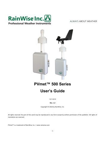
PVmet™ 500 Series
The PVmet-500 is a precision weather station tailored for the photovoltaic industry, measuring parameters such as solar irradiance, module temperature, wind speed and direction, barometric pressure, humidity, ambient temperature, and precipitation. It utilizes Modbus communication over RS-485 and complies with SunSpec standards.
Initial installation should occur at ground level to verify component functionality. The station features a NEMA-rated enclosure on a PVC mast. Proper siting is essential to prevent measurement errors from obstructions or topography.
Sensors must be placed away from heat sources and obstructions. Humidity and temperature sensors should be 1.25m to 2m above large surfaces and away from walls for adequate airflow.
Install anemometers 10m above ground and at least 10 times the height away from obstructions to reduce turbulence effects.
These require careful installation to avoid errors from reflected light or shading, ensuring maximum sky exposure and proper leveling.
Mount these near the panel center using thermally conductive adhesive tape for accurate temperature readings.
The bottom mast is mounted with U-bolts and should be vertical. The topmast can rotate independently for alignment.
Verify all connections before powering to prevent damage. The enclosure has cable entry slots with rubber seals to minimize dust and water intrusion.
The PVmet-500 requires a 10-30VDC, 1.5W power supply, with reverse input and overcurrent protection. Earth connection is crucial for protection and noise mitigation.
RS-485 is chosen for reliability and noise immunity. Proper wiring and termination are essential for effective communication.
The device supports Mini Aervane and ultrasonic anemometers, requiring RJ-45 connections and proper alignment.
Compatible with any 0.2mm tipping bucket rain gauge using a normally open switch contact.
Designed for robust operation in various environments, with specific sensors and electrical specifications ensuring reliable performance.
The BOM sensor cable is shielded to reduce noise and protect against ESD/EMI, with the shield connected at the main board. Proper connection is crucial for accuracy, with a temperature derating factor applied if cable length is extended.
Supports three solar irradiance inputs with a maximum voltage output of 1.5V. Cables should be routed away from noisy equipment, with shielded wires terminated at the PVmet-500 shield connection.
Operates with an RS-485 SunSpec compliant host, communicating via Modbus RTU interface. Default settings include a baud rate of 9600 or 19200 bps, no parity, and a slave address of 60.
Follows SunSpec models 302, 303, and 307 for solar irradiance, BOM temperature, and meteorological data, each with specific data characteristics and addresses.
Configured using Modbus registers outside the standard SunSpec block. The default Modbus address is 60, adjustable if necessary. Irradiance sensitivity settings and baud rate can also be modified.
Operates in temperatures from -40°C to 60°C, supporting various sensors with specific accuracy and resolution parameters. Made with RoHS compliant materials and features a robust enclosure.
Includes a full SunSpec map for the PVmet-500, detailing register addresses and data types.
Provides a detailed register map for environmental measurements such as rainfall, snowfall, precipitation type, electric field, surface wetness, soil moisture, and various irradiance types, including back of module temperature.
Outlines Modbus device address, sensitivity settings for solar irradiance sensors, baud rate options, and wind sensor selection.
Support is available through RainWise Inc. with contact details provided. The product includes a two-year warranty covering defects in materials and workmanship, excluding damage from misuse, accidents, or unauthorized repairs. The warranty process includes return instructions.
- Measured Rainfall: int16 mm
- Snowfall: int16 mm
- Precipitation Type: int16 mm
- Electric Field: int16 V/m
- Surface Wetness: int16 kΩ
- Soil Moisture: int16 %
- Global Horizontal Irradiance: uint16 W/m²
- Plane-of-Array Irradiance: uint16 W/m²
- Diffuse Irradiance: uint16 W/m²
- Direct Irradiance: uint16 W/m²
- Back of Module Temperature: int16 °C
Ensure proper packaging when returning equipment to avoid damage during shipping, which is not covered by the warranty.
Catalog excerpts
ALWAYS ABOUT WEATHER PVmet™ 500 Series User’s Guide 10/11/2018 All rights reserved. No part of this work may be reproduced in any form except by written permission of the publisher. All rights of translation are reserved. PVmet™ is a trademark of RainWise, Inc. | www.rainwi
Open the catalog to page 1
INSTALLING THE WEATHER STATION 4 Siting Requirements and Considerations 4 Relative humidity and Temperature SENSOR 5 Solar Irradiance SENSORS 6 Back of module temperature sensors 7 Relative Humidity and Temperature 14 Back of Module Temperature Sensor 14 Supported SunSpec models 17 Modbus Address (Register 200) 20
Open the catalog to page 2
Irradiance Sensitivity Settings (Registers 202,203,204) Baud Rate (Register 205) 21 Wind Sensor Selection (Register 206) 21 Rainfall Accumulator (Register 215) 22 Ambient Air Temperature Sensor 23 Solar Irradiance input 24 Full device settings register map 27 Bottom Mast Dimensions 28
Open the catalog to page 3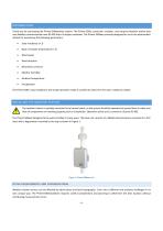
Thank you for purchasing the PVmet-500weather station. The PVmet-500is a precision, modular, and compact weather station that uses Modbus communication over RS-485 that is SunSpec compliant. The PVmet-500was primarily designed for use in the photovoltaic market for monitoring the following parameters: • Back of module temperature (x 3) • Wind speed • Wind direction • Barometric pressure • Relative Humidity • Ambient temperature The PVmet 500's easy installation and simple operation make it a preferred choice for the solar irradiance market. The weather station is typically mounted out of normal...
Open the catalog to page 4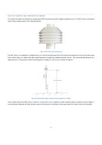
RELATIVE HUMIDITY AND TEMPERATURE SENSOR The relative humidity and ambient air temperature (RHT) are measured with a digital integrated circuit. The RHT sensor is protected within white slopped plastic solar reflecting shields. Figure 2: RHT sensor solar shield housing The RHT sensor is susceptible to radiated heat, so it must be located away from heat producing equipment and must be kept away from surfaces that can radiate heat after being exposed to sunlight for extended periods of time. The recommended distance to a large surface (i.e. the ground, cement mounting pad or rooftop) is 1.25m to...
Open the catalog to page 5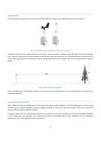
ANEMOMETER An anemometer can be attached to the top of the PVmet-500Series in place of the supplied top cap as seen in Figure 4. Figure 4: PVmet-500Series with a Miniaervane and ultrasonic anemometers Installation instructions are included with each anemometer. The anemometer is typically located 10m above the ground. Buildings, trees, and other obstructions can cause turbulent air which may impact the accuracy of the wind speed/direction measurements. To reduce added inaccuracies the anemometer must be located greater than 10x the height away from any obstructions as shown in Figure 5. Figure...
Open the catalog to page 6
P.O.A. sensors can be mounted to the solar array or separately. If the solar panels are mounted on a tracking system, then the P.O.A. sensor must also be mounted on the tracking system. If the solar panels are not on a tracking system, then the angle of the panels can be measured and the P.O.A. sensor set to the same angle but will have to be readjusted if the panels alignment is changed seasonally. For diffuse or ground reflected sensors follow the instructions that come with the sensor. Each solar irradiance sensor will come with directions for proper mounting and they should be followed carefully....
Open the catalog to page 7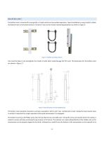
MOUNTING MAST The bottom mast is mounted first using bolts or U-bolts which can be provided separately. Typical installation is using U-bolts to attach the bottom mast to horizontal sections of Unistrut® close to the inverter monitoring equipment as shown in Figure 6. Figure 6: Possible mounting solutions Care must be taken to not overtighten the U-bolts or bolts which could damage the PVC mast. The dimensions for the bottom mast are shown in Figure 17. Figure 7: Mast dimensions in inches [millimeters] The bottom mast should be mounted as vertical as possible in both X and Y axis. Verified with...
Open the catalog to page 8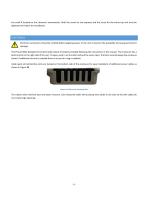
the small N located on the ultrasonic anemometer. Both the screw for the topmast and the screw for the entire top unit must be tightened to finalize the installation. ELECTRICAL Electrical connections should be verified before applying power to the unit to prevent the possibility of causing permanent damage. The PVmet-500is designed to be electrically robust if properly installed following the instructions in this manual. The enclosure has a built-in latch on the right side of the unit. To open, push in on the latch and pull the cover open. This latch securely keeps the enclosure closed, if additional...
Open the catalog to page 9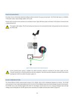
POWER REQUIREMENTS The power circuit is electrically isolated providing excellent protection from ground loop faults. The PVmet-500 requires a 10-30VDC, 1.5W power supply. Large wattage supplies can be used. Reverse input and overcurrent protection are provided on board. Figure 99 shows proper termination of the power connections with a single point ground. The supply is fully isolated. The 0V and Earth ground inputs are not connected internally. Earth ground must be connected to the PVmet-500. Figure 9: Power connections with a single point ground If the incoming power wiring is shielded, the...
Open the catalog to page 10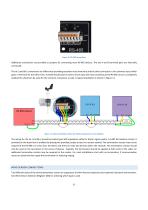
Additional connections are provided as jumpers for connecting more RS-485 devices. The two A and B terminal pairs are internally connected. The A(-) and B(+) connections are differential providing excellent noise immunity and the third connection is the common input which gives a reference for the other lines. A shield should also be used to shunt away the noise and because the RS-485 circuit is completely isolated the shield can be used for the common connection as well. A typical installation is shown in Figure 11. Figure 11: Typical installation where the shield and ground are used together...
Open the catalog to page 11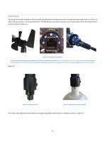
MINIAERVANE The typical PVmet-500 installation will come with the Miniaervane anemometer which provides the wind speed from 0 to 67m/s as well as the wind vector in 16 cardinal directions. The Miniaervane uses RJ45 connectors on the main board and on the bottom of the sensor as shown in Figure 12. Figure 12: Miniaervane connections To install the Miniaervane remove the loosen the cap screw and remove the cap. Also, remove and discard the red cable support plug in the top of the mast. Connect the RJ-45 connector to the sensor and slide the Miniaervane onto the mast making sure the slot on the...
Open the catalog to page 12All EKO Instruments catalogs and technical brochures
 MS-80SH Plus+
2 Pages
 HF-01S
2 Pages
 ML-01
2 Pages
 MS-321LR
32 Pages
 MS-56
2 Pages
 MS-093
27 Pages
 MS-90 Plus+
4 Pages
 MS-60A Pyranometer
4 Pages
 MS-80M Pyranometer
3 Pages
 MS-80A Pyranometer
3 Pages
 MS-80S Pyranometer
4 Pages


Archived catalogs
 MS-80U Pyranomete
3 Pages
 PYRANOMETERS ML-01, ML-02
2 Pages

- Measuring device
- CMOS camera module
- Resistance temperature sensor
- Data logger
- Monitoring camera system
- Temperature datalogger
- Portable tester
- Pt100 temperature transducer
- Thermocouple temperature transducer
- USB datalogger
- HD camera module
- Wireless datalogger
- Datalogger without display
- Metal stand
- RTD temperature sensor
- Monitoring datalogger
- PoE imager
- Measurement monitoring module
- Compact tester