
- Catalogs
- EKO Instruments
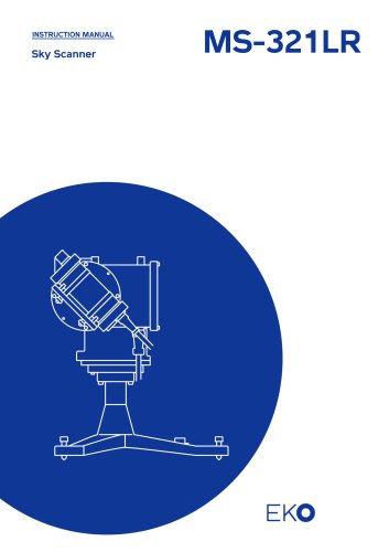
- MS-321LR


MS-321LR
MS-321LR
- Read and understand the manual thoroughly before using the instrument. Warranty is void if the product is used contrary to the manual's instructions or if unauthorized modifications are made.
- Contact information for EKO offices in Asia, Europe, and North America is available for support.
- The manual is copyrighted and was issued on December 5, 2016. Compliance with WEEE and RoHS Directives is noted.
- Ensure the base or mast can support the Sky Scanner to prevent accidents. Verify correct power supply voltage and type before use. Avoid contact with the instrument during operation to prevent injury.
- The Sky Scanner MS-321LR measures luminance and radiance by dividing the sky hemisphere into 145 points, based on CIE108-1994 recommendations. Software displays and saves these values, including sun position data.
- Includes driving part, sensors, cables, software CD-ROM, instruction manual, and calibration report.
- Detailed descriptions of parts and their functions are provided. Installation requires a clear view for sensors and proper orientation to True-North/South. Leveling and securing the Sky Scanner is crucial for accurate operation.
- Choose a location free from obstructions and reflective surfaces. Ensure the setup base can support the Sky Scanner's weight. Use leveling screws to ensure horizontal positioning.
- Ensure cables are connected properly and have enough slack to accommodate movement. For extended communication cables longer than 20m, an RS422/RS232C converter is necessary.
- To install the software, create a folder on your hard disk and copy the SkyScanner.exe file into it. Uninstallation is straightforward by deleting the SkyScanner.exe file.
- The software interface includes a menu bar with commands for file operations, view settings, measurement controls, and help. A toolbar provides quick access to frequently used functions.
- Start the SkyScanner.exe software and configure measurement settings through the Measurement Settings Dialog. Measurements can be taken manually or automatically, with data displayed in various formats.
- Data files can be opened and viewed in different display modes. Printing options are available for data displayed in the measurement window.
- In case of communication errors due to power outages or cable disconnections, the software will indicate an error, and the data will be saved as a missed measurement.
- Data files are stored in CSV format, named using the format 'SSyymmdd.csv'. The header includes details such as title, firmware version, measurement date, and location coordinates.
- Regular maintenance includes checking and adjusting the driving part position, cleaning the optical sensor, inspecting cable conditions, replacing silica gel, and rebooting the PC monthly. Troubleshooting involves checking power supply, cable connections, and ensuring the software operates correctly.
- Main Unit: Completes a full scan in 4.5 minutes, covering 145 points. Driving Part: Features a stepping motor with high accuracy and resolution. Sensor Part: Includes luminance and radiance sensors with specific aperture and tilt angles.
- Version 1.0.0.1 is compatible with Windows XP through 10, requiring a minimum of Pentium 200MHz CPU and 32MB memory.
- Specifications for output, power, and communication cables are provided. Communication cables can be extended up to 15m, and power supply cables up to 100m.
- Includes options for extended communication and power cables, and converters for RS422 communication over long distances.
Catalog excerpts

INSTRUCTION MANUAL
Open the catalog to page 1
2. Important User Information 2 2-3. About Instruction Manual 3 5- 1. Parts Name and Descriptions 7 6- 5. Data File Format 23 EKO INSTRUMENTS CO., LTD. Sky Scanner MS-321LR Instruction Manual V5
Open the catalog to page 2
2. Important User Information Thank you for using EKO Products Make sure to read this instruction manual thoroughly and to understand the contents before starting to operate the instrument. Keep this manual at safe and handy place for whenever it is needed. For any questions, please contact us at one of the EKO offices given below: 2- 1. C on tac t I nfo r mati on EKO INSTRUMENTS CO., LTD. Asia, Oceania Region www.eko.co.jp [email protected] EKO INSTRUMETNS Co., Ltd. 1-21-8 Hatagaya, Shibuya-ku 95 South Market Street, Suite 300 Europe, Middle East, Africa, South America Region www.eko-eu.com [email protected]...
Open the catalog to page 3
2- 3. A bo ut I ns tr uc ti o n Ma nu al Copy Rights Reserved by EKO INSTRUMENTS CO., LTD. Making copies of whole or parts of this document without permission from EKO is prohibited. This manual was issued: Version Number: 2- 4. Env i ro nm ent 1. WEEE Directive 2002/96/EC (Waste Electrical and Electronic Equipment) This product is not subjected to WEEE Directive 2002/96/EC however it should not be mixed with general household waste. For proper treatment, recovery and recycling, please take this product(s) to designated collection points. Disposing of this product correctly will help save valuable...
Open the catalog to page 4
3. Safety Information EKO Products are designed and manufactured with consideration for safety; however, please make sure to read and understand this instruction manual thoroughly to be able to operate the instrument safely in the correct manner. WARNING CAUTION Attention to user; pay attention to the instructions given on the instruction manual with this sign. Installation Base or Mast should have enough load capacity to mount the Sky Scanner. Fix the main body firmly to the base or mast with bolts and nuts. Instrument may drop by gale and/or earthquake and may invite unexpected accidents and...
Open the catalog to page 5
4. Introduction Sky Scanner MS-321LR is designed to measure luminance and radiance using sensor with 11 degree aperture angle and dual-axis control driving part by dividing the sky hemisphere into 145 points. 4- 1. Mai n F un c ti ons 1. Sky Scanner MS-321LR tracks the sky hemisphere by dividing it into 145 points, measuring luminance and radiance in 4.5 minutes using the sensor with 11 degree aperture angle and dual-axis control driving part. The measurements of 145 points are based on the CIE108-1994 recommendation. (CIE - International Lighting Commission, IDMP - International Daylight Measurement...
Open the catalog to page 6
Check the package contents first; if any missing item or damage is noticed, please contact EKO immediately. Table 4-1 Package Contents EKO INSTRUMENTS CO., LTD. Sky Scanner MS-321LR Instruction Manual V5
Open the catalog to page 7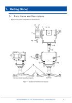
5. Getting Started 5- 1. Pa rts Na me an d Des c r i pti o ns Each part name and its main functions are described below. Side View (Optical Sensor Mounting side) Back View Figure 5-1. Sky Scanner Parts Name and Functions EKO INSTRUMENTS CO., LTD. Sky Scanner MS-321LR Instruction Manual V5
Open the catalog to page 8
Table 5-1. Parts Name and Functions No. Parts Name Optical Sensor Measures both luminance and radiance at each point. Luminance Sensor Measures luminance. Radiance Sensor Measures radiance. Driving Part Base structure to mount the Sky Scanner. Spirit Level For leveling the Sky Scanner in a horizontal position. Leveling Screws Directs optical sensor to the 145 measurement points that are defined by altitude and azimuth angle of sky hemisphere. Adjustable screws to position the Sky Scanner in horizontal position. Use these screws to bring air bubble to the center of spirit level. For fixing the...
Open the catalog to page 9
Installation Location & Setup Conditions Install the Sky Scanner in a place where nothing obstructs the view of the sensors. The ideal mounting position for Sky Scanner is a location which has a free field-of-view without any obstructions (such as buildings, trees, and mountain). In practice, it might be difficult to find such locations; therefore, some practical recommendations on how to minimize undesired effects of reflecting or obstructing surfaces are given next: Select a mounting position which it is free from obstructions at 5° above horizon. The setup location should be easily accessible...
Open the catalog to page 10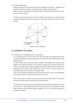
Preparing Installation Base Prepare a setup base with fixing holes for the anchor bolts (M8) as shown below. installation position will be important, thus carefully check the position of the anchor bolts. Make sure that the mounting base can hold total weight of the Sky Scanner itself and the sensors mounted on the Sky Scanner. The anchor bolts must be attached to hold the Sky Scanner on the setup base. To avoid unexpected accidents or damage due to strong wind or gale, make sure to fasten the tripod on the stage or ground securely. Figure 5-3. Anchor bolt position Put Sky Scanner on the installation...
Open the catalog to page 11
2) Adjust the leveling screws to setup the tripod in horizontal position. Use the leveling screws to bring the air bubble inside the spirit level in the center of the circle indicated. 3) Once the position and horizontal level for the Sky Scanner has been completed, fix the Sky Scanner securely onto the mounting base using attached M8 bolts. 4) Attach the optical sensor on the mounting plate. After placing the optical sensor on the V-block attached on the mounting plate, secure the optical sensor with attached fixing rings. 5) Install personal computer in a safe and suitable area. EKO INSTRUMENTS...
Open the catalog to page 12
5- 4. C abl e Co nnec ti o ns 1. Output Cable Connection Connect the connectors on the sensor side and Driving Part side with provided signal cable. Make sure the cables are routed with sufficient length for Sky Scanner movement to prevent cable from getting caught or tangled on the leveling screws, etc. First place the signal cable on the Driving Part axis then connect the cable ends to each connectors. Make sure the signal cable will not get caught on the leveling screws when the Driving Part turns. Figure 5-4. Signal Cable Position 2. Communication Cable Connection Connect the Sky Scanner...
Open the catalog to page 13All EKO Instruments catalogs and technical brochures
 MS-80SH Plus+
2 Pages
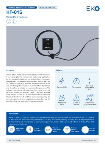 HF-01S
2 Pages
 ML-01
2 Pages
 MS-56
2 Pages
 MS-093
27 Pages
 MS-90 Plus+
4 Pages
 PVmet™ 500 Series
29 Pages
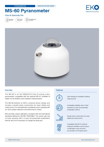 MS-60A Pyranometer
4 Pages
 MS-80M Pyranometer
3 Pages
 MS-80A Pyranometer
3 Pages
 MS-80S Pyranometer
4 Pages



Archived catalogs
 MS-80U Pyranomete
3 Pages
 PYRANOMETERS ML-01, ML-02
2 Pages

- Temperature probe
- Measuring device
- CMOS camera module
- Resistance temperature sensor
- Data logger
- Monitoring camera system
- Temperature datalogger
- Portable tester
- Pt100 temperature transducer
- Thermocouple temperature transducer
- USB datalogger
- HD camera module
- Wireless datalogger
- Datalogger without display
- Metal stand
- RTD temperature sensor
- Monitoring datalogger
- PoE imager
- Measurement monitoring module
- Compact tester