PFR

PFR
PFR System Overview
The PFR system consists of plastic cable carriers designed for protection and guidance of cables and hoses. It features a closed tube design that offers excellent protection against dirt and mechanical damage such as chips.
Types and Dimensions
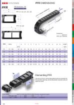
The PFR series includes types 121, 122, 123, 221, 222, 223, and 322, each with specific dimensions and load capacities. Key parameters include pitch, flange sizes, and weight per meter. For example, PFR 121 has a pitch of 75/150 mm, weighs 0.7 kg/m, and supports a load of 61 kg/m. Larger types like PFR 322 have a pitch of 150/300 mm and weigh 3.2 kg/m.
Design Features
- Closed plastic tube design for dirt and chip protection.
- Types 123, 223, and 323 have two separate chambers for cable segregation.
- Metallic finish versions are available on request, offering high scratch resistance, heat resistance, and an attractive shiny surface, suitable for environments with hot chips and sparks.
Connectors and Assembly
Plastic connectors can be installed at any point along the chain, allowing sections to remain static if needed. Headside flange connectors enable mounting on the top or front of machines, with options for combined frontal and end connections. Steel flanges are also available upon request.
Ordering Examples:
- Plastic connectors on both ends: PFR 121 / 75 x 1505 / K K
- Plastic connector and headside flange: PFR 121 / 75 x 1505 / K SFA
- Steel flanges N and A: PFR 121 / 75 x 1505 / N A
Dismantling Procedure
Dismantling tools use 3x12 mm pins inserted into designated openings. These tools compress and pull apart the carrier for easy disassembly.
Pretension and Installation Parameters
- Pretension is generally 25 mm/m, except for PFR 322 which is 20 mm/m.
- Typical pitch and length parameters are specified per type.
Load and Length Specifications
The document includes load diagrams and free carrying length data for galvanized and standard PFR types, indicating maximum permissible loads and chain lengths for safe operation.
Summary of Critical Parameters (Selected Types)
| Type | Pitch (mm) | Flange Dimensions (a,b,c,d,f,g,h,i,k) | Load (kg/m) | Weight (kg/m) |
|---|---|---|---|---|
| 121 | 75 / 150 | 35, 23, 23, 35, 35, 6, 0, 5.1, 9 | 61 | 0.7 |
| 122 | 75 / 150 | 35, 23, 38, 35, 50, 6, 20, 5.1, 9 | 56 | 1.2 |
| 123 | 75 / 150 | 35, 23, 30, 35, 75, 6, 45, 5.1, 9 | 56 | 1.5 |
| 221 | 100 / 200 | 50, 34, 36, 50, 50, 8, 20, 6.1, 11.5 | 56 | 1.6 |
| 222 | 100 / 200 | 50, 34, 86, 50, 100, 8, 70, 6.1, 11.5 | 56 | 2.1 |
| 223 | 100 / 200 | 50, 34, 66, 50, 150, 8, 120, 6.1, 11.5 | 56 | 2.8 |
| 322 | 150 / 300 | 65, 57, 134, 75, 150, 10, 120, 8.1, 15 | 56 | 3.2 |
Recommendations and Best Practices
- Use metallic finish PFR types in environments with hot chips or sparks for enhanced durability.
- Install plastic connectors as needed to create static sections within the chain.
- Follow pretension guidelines to ensure proper installation and function.
- Use dismantling tools with specified pins for safe and efficient disassembly.
Catalog excerpts
Order infos travel 3 m, bend radius 200 mm, plastic connectors, arrangement hanging order example: MARATHON ALLROUND ELTOLA The pins (3x12mm) of the dismantling tools are inserted into the provided openings, dismantling tools compress and pull apart the carrier. Design guidelines
Open the catalog to page 1
LOAD DIAGRAM Design guidelines The plastic end connector can be installed at any point in the chain, whereby a portion of the tube can serve as a static line. plastic connector plastic connector on both sides Headside flange connector PFR The headside bracket is used for assembly on top or front of the machine. A combination of frontal and end connection is possible. Order example: headside flange connector plastic connector and headside flange Order example: free carrying length Lf / (m) 0 PFR with metallic surface are deliverable only on request. Order infos The plastic tube PFR is a closed...
Open the catalog to page 2All EKD Systems GmbH catalogs and technical brochures
 DRAG CHAINS
6 Pages
 SFK
SFK2 Pages
 GKA
GKA6 Pages
 PKK
PKK18 Pages
 Catalogue
128 Pages
 Kolibri
30 Pages
 PLE
PLE14 Pages
 SLE
SLE18 Pages
 Main Catalogue
126 Pages