- Catalogs
- EKD Systems GmbH
- Catalogue

Catalogue

Catalogue
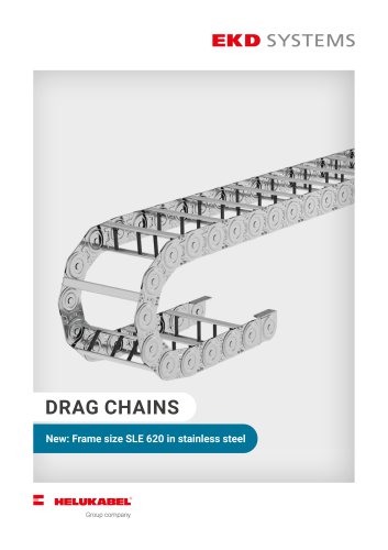
EKD SYSTEMS, part of HELUKABEL GmbH since 2022, specializes in manufacturing energy chains since 1970. They offer a variety of steel and plastic energy chains, including custom solutions with cables, connectors, and mounting kits. Their services encompass selection, design, assembly, and commissioning.
Energy chains are available in steel and plastic. Plastic is preferred for its chemical resistance, lightweight, and cost-effectiveness, while steel is used for extreme payloads and mechanical requirements. The cross-section for wires is calculated based on motion, environmental conditions, and other factors.
- Material Selection: Plastic is preferred for general applications; steel is for high-stress conditions.
- Cross-Section Calculation: Requires clearance for each line, with specific percentages for round cables, flat cables, and hoses.
- Bending Radius: Determined by the minimum permissible bending radius of cables and hoses, installation space, and polygon oscillation.
- Energy Chain Length: Calculated based on travel distance, bending radius, and connector position.
- Pretension and Sag: Energy chains are supplied with pretension to increase free carrying lengths. Sag is influenced by load, material, and environmental conditions.
Different arrangements include normal, multiaxial, free overhang, and moved end downside, each with specific applications and limitations.
EKD offers systems like SYSTEM MARATHON for unlimited travel and gliding energy chains for specific applications. Accessories include support rolls, support rails, and carriages for enhanced performance.
- Nested Travel: Utilizes multiple energy chains with different bending radii for various cables and hoses, moved by a common driver.
- Opposite Running: Two energy chains run synchronously or independently in one line, increasing the number of moved lines without extra space.
- Gliding Arrangement: Used when the free carrying length is exceeded, requiring a trough and sliders for increased lifespan.
- Vertical Travel: Common in systems with multiple linear axes, using chains without pretension, with weight supported by the straight part of the chain.
- Vertically Hanging: Used in elevators and doors, with energy chains predominantly tensile stressed.
- Horizontal Arrangement: Chains lie on their side for space constraints or long traverses at low speeds.
- Driving Apart: Requires custom calculation of chain length based on application needs.
- Circle Arrangement: Involves circular motion with a part of the chain manufactured with an opposite bending radius, allowing rotation up to 520°.
- Use highly flexible cables with permissible bending radii, laid twist-free.
- Strain relief should be attached at the driver end for long distances and high speeds.
- Hydraulic hoses require special attention to jacket material and structural design.
- Integrated: Directly attached to plastic dividers, space-saving.
- Combined: Offers distance from bending areas with simple installation.
- Separate: Recommended for high dynamic loads, allowing easy length compensation.
- Energy chains must be used according to engineering design and safety rules.
- Grounding is necessary for electrically conductive chains.
- Improper handling can lead to damage, especially in abrasive conditions.
- Selection based on cable diameter and number, with clearance for cables and hoses.
- Chain length depends on travel distance, calculated with a specific formula.
- Order examples provided for different chain types and configurations.
Specifications:
1. Kolibri HEIGHT 15: Inner height 10, inner width 10 to 39. Weight: 0.35 kg/m. Free carrying length: 0.9 m at 0.9 kg/m load. Pitch: 20.
2. Kolibri HEIGHT 22: Inner height 16 to 22, inner width 15 to 48. Weight: 0.20 kg/m. Free carrying length: 1.3 m at 1.5 kg/m load. Pitch: 30.
3. Kolibri HEIGHT 30: Inner height 23 to 24, inner width 18 to 109. Weight varies from 0.50 to 0.87 kg/m. Free carrying length: 1.5 m at 2.0 kg/m load. Pitch: 35 to 40.
4. Kolibri HEIGHT 40: Inner height 31, inner width 48 to 60. Weight varies from 0.91 to 1.05 kg/m. Free carrying length: 2.0 m at 1.0 kg/m load. Pitch: 45.
Kolibri energy chains are available in various types including standard, open, closed, and rigid types. They feature integrated connectors and offer different bend radii options ranging from 35 to 230 depending on the model.
Each model has specific order examples provided, indicating the type, radius, and length. For instance, Kolibri 15.037.3 / 30 x 1000 and Kolibri 30.125.0 / 100 x 1225.
Some models offer quick and toolless assembly with Snap connectors, allowing for easy installation. The chains are designed for durability and flexibility in various industrial applications.
The document provides detailed specifications on the materials used, ensuring the chains meet industry standards for strength and reliability.
This document provides detailed specifications and guidelines for the Kolibri energy chain systems, focusing on various models and their configurations. It includes information on dimensions, weight, bend radius, and installation procedures.
- Kolibri 50 Series: Includes models like 50.065.0, 50.095.0, and 50.125.0. These models have bend radii ranging from 75 to 250, weights between 1.30 kg/m to 1.52 kg/m, and a free carrying length of 2.4 m at a 1.0 kg/m load.
- Kolibri 65 Series: Models such as 65.095.1 and 65.135.1 feature bend radii from 125 to 400, weights from 2.2 kg/m to 2.7 kg/m, and a free carrying length of 2.75 m at a 1.0 kg/m load.
- Flap Stays: Installation involves snapping the flap stays into place with slight pressure. Removal requires unlocking the tongue and pushing out the stays.
- Horizontal Dividers: These are slid onto vertical dividers and can be locked or disassembled using a screwdriver.
- Energy Chain Mounting: The energy chain can be mounted using horn stays and integrated connectors. Snap assembly allows for quick installation.
Kolibri energy chains are maintenance-free but should be monitored for wear due to environmental conditions. Replacement is necessary if wear is observed.
Order examples are provided for each model, specifying type, radius, and length. The document includes part numbers and dimensions for various components.
The document outlines various PKK types and their specifications, including dimensions, friction coefficients, and design features. The friction coefficient is noted as 0.2 to 0.25. PKK types are categorized by their design features such as extension stays, closed designs, and sliders for gliding arrangements.
The assembly and disassembly procedures for PKK energy chains are detailed. This includes instructions for lengthening or shortening link bands, assembling stays, and installing covers. Specific tools and methods are recommended for efficient assembly and disassembly.
The document provides design guidelines for various PKK models, emphasizing the importance of correct assembly to ensure optimal performance. It highlights the use of integrated connectors and strain reliefs for secure installations.
Recommendations include conditioning sliders before installation and ensuring correct overlap of covers. The document advises on the use of multiband energy chains for carrying large hoses or additional components.
The tables provide detailed dimensions for different PKK models, including height, inner height, and stay lengths. They also specify the bending radius and weight for each model.
Key parameters such as the minimum bend radius for sliders and the importance of avoiding mechanical damage during packaging and handling are emphasized. The document also notes that the smallest radius of each PKK dimension is not suitable for sliders.
- Integrated Strain Relief: Mounted directly on the vertical divider of the energy chain's first link, ensuring tension does not unlock the divider. Recommended to add extra chain length to prevent premature wear.
- Combined Strain Relief: Offers a balance between distance and space-saving installation. Allows lateral insertion and extraction of strain relief elements.
- Separate Strain Relief: Suitable for high dynamic loads and large line diameters, providing sufficient distance from the chain.
- Anchor Profile (ZLP): Aluminum profile for mounting strain relief elements, allowing customizable distance and positioning.
- Strain Relief Stay (PZL): Based on the plastic vertical divider, accommodates multiple elements.
- Blue Ribbon (ZLB 24): Cable tie for diameters 7-35 mm, can fix lines singly or in multiples.
- Push Anchor (ZLS 10): Inserted into profiles, lines fixed with standard cable ties.
- Cable Anchor (ZLA 8): Pushed onto the stay, fixed with cable ties at various altitudes.
- Horn Stay (ZHS 10): Inserted transversely into the profile, locked by rotation, lines fixed with cable ties.
- PKK energy chains are maintenance-free but should be monitored for wear due to ambient conditions.
- For long travels or circular motion, chains may have sliding elements that require regular checks and replacement when worn to 1-2 mm thickness.
- Detailed part numbers are provided for various PKK components, indicating options with and without pretension.
- Link Bands: To adjust the length, disengage spreaders and remove or add chain links. Stays are installed and locked by shifting horizontally.
- Plastic Inserts and Foam: Inserts are positioned laterally, and foam is pushed into aluminum profiles before assembly.
- Plastic Divider PZ: Dividers are hooked into position and can be adjusted laterally. Dismantling involves pulling or pushing sideways.
- Telescopic Horizontal Divider: Adjustable in length and vertically fitted on the PZ.
- Energy Chain Mounting: Integrated connectors allow mounting with any link. Flange connectors offer various mounting options.
- Travel: Maximum travel is twice the free carrying length, with support rollers increasing this value. Gliding arrangements allow up to 100 meters.
- Speed and Acceleration: Standard designs are limited to 1m/s. High dynamic loads require hardened materials.
- Temperature: Operating range is -20°C to 600°C, with stainless steel options available.
The document outlines the specifications for energy chain systems, focusing on components like aluminum troughs and slide bars. It includes detailed measurements and part numbers for various components such as alu-trough angles, slide bars, and distance profiles. The document also provides weight specifications for each component.
Instructions are provided for assembling connection angles and gliding applications. The document describes the process of aligning grooves and fixing connection angles, as well as the installation of slide bars for gliding applications.
The document includes design guidelines for different energy chain systems, such as the Kolibri and SYSTEM MARATHON. It discusses the importance of selecting the right energy chain based on travel distance, speed, and environmental conditions. The guidelines also cover the use of gliding arrangements and the benefits of SYSTEM MARATHON in reducing friction and wear.
Standards for materials and components are mentioned, including the use of DIN standards for screws, washers, and nuts. Recommendations for using specific energy chains and troughs based on application requirements are provided.
The document contains tables listing various components with their part numbers, dimensions, and weights. For example, the alu-trough angle 120x3000 has a weight of 3.5 kg, and the slide bar 20x20x3000 weighs 1.2 kg. Another table lists distance profiles for aluminum troughs with specifications like energy chain dimensions and weights.
The SYSTEM MARATHON is highlighted for its design that minimizes friction and wear, making it suitable for long travel distances. The SYSTEM ALLROUND is noted for its flexibility, allowing for various movement combinations. The SYSTEM ELTOLA is described as a noiseless and low-wear option for applications requiring fast and noise-sensitive movements.
Examples of applications for these systems include cranes, telescopic systems, and handling equipment. Specific examples like train wash systems and greenhouses are mentioned to illustrate the versatility and adaptability of the energy chain systems.
The document provides an overview of the technical specifications and guidelines for energy chains produced by EKD Systems GmbH. It emphasizes that the catalog reflects the state of the art at the time of publication, and product specifications agreed upon in orders and contracts are binding. All content is copyrighted by EKD Systems GmbH, and reproduction or sharing requires explicit consent.
Energy chains are designed for specific engineering applications and must be used in compliance with operating and safety instructions. Key safety measures include ensuring adequate safeguards to prevent accidental movement and adhering to accident prevention regulations. Special considerations are necessary for explosive hazardous areas.
The document outlines potential issues that can lead to functional errors or damage, such as improper handling during transport and assembly, excessive weight load, operating beyond designed travel distances, and improper line load. It stresses the importance of avoiding interference in the operating area and maintaining appropriate inspection intervals, especially in automated systems.
EKD Systems GmbH is located at Steinhof 47, 40699 Erkrath, with contact details provided for further inquiries.
Catalog excerpts

MARATHON ALLROUND ELTOLA energy chains and energy chain systems in steel and plastics Order infos Design guidelines
Open the catalog to page 1
1970and since 2022 a member of HELUKABEL GmbH. From the founding product energy pipe is formed today a wide EKD SYSTEMS is manufacturer of energy chains since with cables, connectors and mounting kits for every application. The service spectrum ranges from the selection and design of appropriate energy chains, electrical In addition to standardizised series products in steel and plastics special products are a priority of the ekd product range, which are designed and made of materials in Order infos up to plug in speciality products and tailor-made solutions provides the standard of energy chains...
Open the catalog to page 2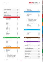
Energy chain systems | Electrical cables | Hoses part numbers Strain reliefs Order informations part numbers part numbers SLS with foam stay SLP with plastic divider Pz SLR with pipe- / rollstays part numbers gliding applications Energy chain systems System Marathon System Allround System Eltola System Reintec PLP with plastic divider Pz PLS with foam stay Safety instructions MARATHON ALLROUND ELTOLA
Open the catalog to page 3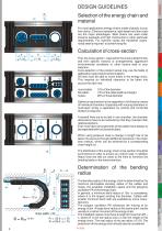
If several lines are to be laid in one chamber, the chamber dimensions have to be restricted so that they maintain their relative positions. Even multi-layer arrangements of flat cables have always to be seperated with horizontal dividers. When using pressure hose a change in length has to be taken into account through additional clearance in the chain bow (radius), which can be achieved by a corresponding chain height (a). The distribution of the energy chain cross-section should be symmetrical in order to ensure an uniform load. In addition heavy lines are laid out close to the links to minimize...
Open the catalog to page 4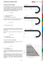
DESIGN GUIDELINES In standard applications the fixed connector of the energy chain is arranged in the middle of the travel distance. The moving connector moves horizontally over the fixed connector between the end positions of the travel. The required length of the energy chain between the first and the last pivoting link is then determined as follows: Order infos If the fixed connector is not in the middle of the travel, the energy chain has to be extended by a displacement of x: L length of the energy chain LV length of travel R bending radius of the energy chain Design guidelines Energy chain...
Open the catalog to page 5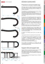
The sag is due to the additional load and the weight of the energy chain. Due to the significantly lower elongation of steel (0.2% linear elongation) compared to plastics the permissible sag of the steel chains is limited lower than for plastic energy chains. On the other hand, the effect on plastic energy chains of a long-term static load with a long unsupported length of the upper strand chains will increase the sag (creeping of plastics). Elevated temperatures and humidity increases this effect. The sag of energy chains is also increased by use-wear. sag The maximum allowable sag can only...
Open the catalog to page 6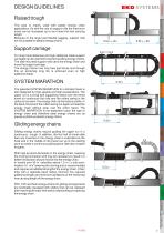
DESIGN GUIDELINES Order infos This type is mainly used with plastic energy chain applications. As with the use of support rolls the maximum travel can be increased up to four times the free carrying length. Because of the larger permissible sagging, support rolls are not suitable for plastic energy chains. Design guidelines Raised trough Support carriage For long travel distances and high additional loads support carriages can be used with reverse travelling energy chains. The side-mounted support rolls carry the energy chain and move the support carriage. The energy chains now only face pull...
Open the catalog to page 7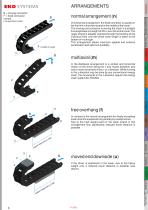
multiaxial (m) In the multiaxial arrangement is a vertical and horizontal motion of the driver along the x-axis (travel direction) and one or more movement in the y- or z-direction. While running in the y-direction may be done by any conventional energy chain, the movements in the z-direction require the energy chain system ALLROUND. Content Design guidelines Order infos In the normal arrangement the fixed connector is usually on the first link in the lower strand in the middle of the travel. The moving end connector is moving the chain in a straight line lengthwise at a height of 2R+c over the...
Open the catalog to page 8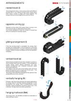
Design guidelines The arrangement of two or more energy chains with different bending radii or even different energy chains makes sense when using a variety of cables and hoses together. The energy chains are moved together by a common driver. Order infos Opposite running means two energy chains running in one line synchronuosly or independent of each other. It is a further possibility to raise the number of moved lines without increasing the necessary space. gliding arrangement (l) If the free carrying length is exceeded, the energy chain changes into a gliding state. In this arrangement, use...
Open the catalog to page 9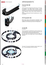
driving apart (a) With energy chains moving apart the calculation of the energy chain length does not follow the usual pattern, but be adapted to the individual requirements of the application. The circular motion is a special form of chain movement. For circle movement a part of the energy chain has to be manufactured with an opposite bending radius R2. The outer radius R3 is derived from the link height, the bending radius of the energy chain R1 and the opposite radius R2. Design guidelines Energy chains are arranged horizontally lying on their side, for example, if the space does not allow...
Open the catalog to page 10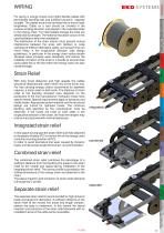
Order infos Design guidelines For laying in energy chains only highly flexible cables with permissible bending radii and sufficient dynamic capacity suitable. The cables have to be laid twist free to move freely lengthwise. Cable on a reel should be unrolled in the reverse winding direction and placed in the extended state in the energy chain. For intermediate storage the lines are ideally laid out straight. The material relaxation occurs in this case facilitates a twist-free installation. The distribution of the chain interior must prevent mutual interference between the wires with dividers...
Open the catalog to page 11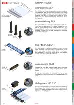
The aluminum anchor profile is used to mount various strain relief elements. Both the distance to the energy chain as well as the positioning of the strain relief elements can be easilz designed. The length of the anchor profile and the drilling dimensions are determinded by the dimensions of the energy chain. strain relief stay ZLS The strain relief stay was developed for anchoring the blue ribbon and the cable anchor. The design of the strain relief stay is closely based on the plastic divider (PZ). It is installed laterally into the anchor profile or a commercially available C-profile and...
Open the catalog to page 12All EKD Systems GmbH catalogs and technical brochures
 DRAG CHAINS
6 Pages
 PFR
PFR2 Pages
 SFK
SFK2 Pages
 GKA
GKA6 Pages
 PKK
PKK18 Pages
 Kolibri
30 Pages
 PLE
PLE14 Pages
 SLE
SLE18 Pages
 Main Catalogue
126 Pages