
- Catalogs
- EGE-Elektronik Spezial-Sensoren GmbH
- Inductive Sensors

- Products
- Catalogs
- News & Trends
- Exhibitions
Inductive Sensors

Inductive Sensors
Inductive sensors are used for non-contact detection of metallic objects. They are available in various designs and specifications to suit different applications.
- Collocation: Maintain a minimum separation between sensors. For flush mounting, the lateral separation should be at least the sensor's diameter. For non-flush mounting, it should be twice the diameter. Oppositely mounted sensors require a separation of six times the rated operating distance.
- Torques: Maximum torques for metal and plastic housings are specified to prevent damage during installation. PTFE sensors should be hand-tightened only.
- Serial Connection: Voltage drops are cumulative, reducing operational voltage. Consider switch-on delay times.
- Parallel Connection: Not recommended for two-wire sensors due to added residual currents. For three-wire sensors, the current consumption is cumulative, limited by power supply capacity.
Sensors used for personal security must comply with EN 61508 and be appropriately labeled.
- Series IGVU: Available in M12, M18, and M30 sizes with stainless steel housing, shock resistance, and impact proof. Operating distances vary from 2mm to 10mm, with a supply voltage of 10-30V DC.
- Series IGV: Similar specifications with cable connections and IP67 protection.
- Series IGVW: Climatic-proofed with operating temperatures from -10°C to +110°C.
- Series IGMP: Polar series with climatic-proofing down to -60°C, available in both DC and AC versions.
- Series IGMF: Tropical series with climatic-proofing up to 120°C, available in both DC and AC versions.
- Series IGMW: Steam-proof with similar specifications to IGMF.
Mounting clamps for metal face sensors are designed for impact and shock resistance, allowing for quick and precise sensor replacement. They are available in various sizes and materials.
- Design: Available in M18 and M30 sizes with stainless steel sleeves.
- Voltage: DC 10...30 V and AC 20...250 V options.
- Protection: IP 68 and IP 69, resistant to high-pressure cleaning and steam.
- Operating Temperature: -25 to +120 °C.
- Switching Frequency: Up to 1000 Hz for DC and 25 Hz for AC.
- Design: PTFE housing, available in M30 and Ø 35 sizes.
- Voltage: DC 10...30 V and AC 20...250 V.
- Protection: IP 68 and IP 69, resistant to rolling oil.
- Operating Temperature: -25 to +120 °C.
- Design: Armoured cable with IP 68 plug, available in M30 and Ø 35 sizes.
- Voltage: DC 10...55 V.
- Protection: IP 68 and IP 69, resistant to acid.
- Operating Temperature: -25 to +120 °C.
- Design: Stainless steel sleeve, available in M12, M18, and M30 sizes.
- Voltage: DC 10...30 V.
- Protection: IP 68 and IP 69, moisture resistant.
- Operating Temperature: -25 to +160 °C.
- Design: High temperature up to 250 °C, available in cuboid and Ø 80 mm designs.
- Protection: IP 60 and IP 67.
- Connection: M12 connector with armoured cable.
- High temperature resistance, suitable for harsh environments.
- Various installation options: flush and non-flush.
- Multiple housing materials including PTFE, AISI 316 Ti, and PEEK.
- LED indicators for function and status.
- Proximity Sensors: Available in various designs (M12, M18, M30, Ø80, Ø105, Ø160, Ø200 mm) with DC and AC voltage options. They feature adjustable sensing ranges, increased EMC, and are suitable for demanding environments. Protection class is IP 67, with housing materials including PBT and Aluminium.
- Amplifiers: Models like IKM 120 GSOP and IU 130 are designed for extreme temperatures, offering adjustable operating distances and programmable outputs. They are short circuit proof and have LED indicators for function and standby status.
- Connection Cables: SLG 3-2 and SLG 4-2 cables are used for connecting sensors, with options for flexible aluminium tubing upon request.
- Installation: Sensors can be installed flush or non-flush, with specific operating distances provided for each type. Connection diagrams are included for proper wiring.
- Temperature Considerations: Sensors are designed to operate within specified temperature ranges, with some models capable of withstanding up to 250°C. Deviations in temperature can affect sensor performance, and guidelines are provided for maintaining optimal operation.
- Use amplifiers with high-temperature proximity switches to ensure accurate performance.
- Ensure proper installation and connection using the provided diagrams to avoid operational issues.
- Consider environmental conditions and select sensors with appropriate protection ratings and materials.
- Operating distances and adjustable ranges are specified for each sensor type, with detailed connection diagrams provided for accurate installation.
- Temperature and voltage specifications are critical for ensuring sensor durability and performance.
- Ex Area of Use: The switches are designed for use in Gas Zones 0/1 and Dust Zones 20/21, with specific models also suitable for Zone 2/22.
- Certification: The products are certified under ATEX and IECEx standards, with specific certificate numbers provided for each series.
- Ex Marking: The marking indicates the level of protection against gas and dust explosions, with categories such as Ex ia IIC T6 Ga for gas and Ex ia IIIC T80°C Da for dust.
- Ambient Temperature: The operating temperature ranges vary by zone and temperature class, generally from -60°C to +140°C depending on the model.
- Electrical Specifications: Supply voltage is typically 24 DC ±10%, with rated voltages and currents specified for each model. Switching currents and frequencies are also detailed.
- Housing Material: Materials include AISI 316 Ti, PTFE, PVDF, POM, Br-Ni, PA, and PEEK, providing durability and resistance to environmental factors.
- Protection Rating: The switches have protection ratings of IP 67, IP 68, and IP 69, indicating resistance to dust and water ingress.
- Connection: Various cable types and lengths are available, with options for M12 connectors and specific cable materials like FEP and PUR.
- Design: The switches are available in designs such as M12x1, M18x1, and M30x1.5, with options for flush and non-flush installation.
- Operating Distance: The operating distance varies by design, ranging from 2 mm to 15 mm.
- LED Display: The switches feature LED indicators for operational status, with colors indicating different functions.
- Impact Protection: Some models include impact protection caps for enhanced durability.
- Amplifiers: The document references compatible amplifiers for connection, such as the IKMb 122 Ex series.
This document provides detailed specifications for various electronic components and accessories, including terminal screws, amplifiers, and inductive sensors. It includes information on supply voltage, relay outputs, and hazardous area classifications.
The document lists different types of cable plug housings under the SLG and SLW series, specifying cable lengths, wire configurations, and maximum voltage and current ratings. The housings are available in straight and angular designs, with some models featuring LED indicators.
Technical data includes thread specifications, contact resistance, insulation resistance, and protection ratings (IP 67 and IP 68). The temperature range for operation is specified as -25 to +80°C.
Details on the PG plug system are provided, including connection instructions and specifications for AC and DC configurations. The document emphasizes the importance of disconnecting power before installation.
Information on lock nuts made from brass-nickel, stainless steel, and plastics is included, along with their dimensions and spanner sizes. Mounting clamps for smooth-bodied switches are also described.
The document lists global sales partners and representatives across various countries, providing contact information for EGE-Elektronik Spezial-Sensoren GmbH.
Catalog excerpts

Inductive Sensors
Open the catalog to page 1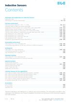
Inductive Sensors Contents Technique and application for Inductive Sensors Application notes Terminology for inductive measurement Extreme environment Metal face sensors Series IGV / IGVU...-C / IGVW Mounting clamp for metal face sensors Series KBM POLAR-Series climatic-proofed – 60 °C Series IGMP / – 80 °C Series IGMP TROPICAL-Series climatic proofed 120 °C Series IGMF / IGMW TROPICAL-Series resistant to cooling fluids 120 °C Series IGFW / INFW TROPICAL-Series resistant to cooling fluids armoured cable Series IGMF / INFW High temperature 120 °C Series IGMT / Series IDT High temperature 160 °C...
Open the catalog to page 2
Inductive Sensors Application notes Sensors Page 3.08 – 3.11 Metal face sensors The inductive proximity switches series IGV are used in areas with heavy-duty mechanical loads at the sensor’s face or where seals between face and housing cannot be used. Chips hitting the front or frequently changing coolants or lubricants do not diminish the function of these proximity switches. The variants with a PTFE coating are particularly well-suited for welding lines and similar environments where sensors are exposed to heavy soiling. Metal face switches are manufactured from stainless steel and are one...
Open the catalog to page 3
Inductive Sensors Technique & Application Terminology Operating principal An inductive proximity switch works with a high frequency oscillating circuit that creates an alternating electromagnetic field on the active sensor surface by means of a coil. When a metallic object nears this field a damping occurs in the oscillating circuit. If this damping exceeds a threshold value, a switching signal is generated. Operating distance The operating distance is the distance between an object and the active sensor surface at which a switching signal is generated. The operating distance depends on the diameter...
Open the catalog to page 4
Inductive Sensors Technique & Application Terminology/Installation and operation Minimum load current Im The operating voltage is the voltage range within EGE sensors function safely. For a constant voltage supply it is important to make sure that the limits are still observed when the residual ripple is included. The minimum load current is necessary for flawless operation with two-wire devices. Short circuit protection The short circuit protection ensures the sensor against destruction through a short circuit on the output. After removal of the fault, the output is reactivated. Where a maximum...
Open the catalog to page 5
Inductive Sensors Technique & Application Installation and operation Collocation When collocating the sensors, a minimum separation must be kept between the devices. When in doubt, a test should be conducted under application conditions. For flush mounting the lateral separation between two sensors must correspond to at least the diameter of the sensor. For non flush mounting, the lateral separation from each other must correspond to at least twice the diameter of the sensor. For oppositely mounted sensors, a minimal separation of six times the rated operating distance should be allowed. Serial...
Open the catalog to page 6
Inductive Sensors Probes Compact models Amplifiers EGE-ELEKTRONIK SPEZIAL-SENSOREN GMBH TEL. +49 (0)4346 / 41580 . ege-elektronik.com
Open the catalog to page 7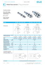
INDUCTIVE SENSORS Series IGVU Metal face sensors | Plug connection Proximity switches M12 / M18 / M30 One piece stainless steel housing DC 10...30 V Shock resistant Impact proof ID-No. Type Supply voltage [V] Switching current [mA] Short circuit proof Reverse protection Voltage drop max. [V] Current consumption [mA] Switching frequency [Hz] Ambient temperature [°C] EMC-class Protection [EN 60529] LED display Housing material Connection The specified operating distance (sn) applies to ferromagnetic objects (ST37). Operating distance sn Switching output PNP connecting cable type SLG 3-2 (Z01076),...
Open the catalog to page 8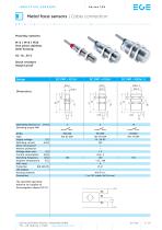
INDUCTIVE SENSORS Metal face sensors | Cable connection Proximity switches M12 / M18 / M30 One piece stainless steel housing DC 10...30 V Shock resistant Impact proof ID-No. Type Supply voltage [V] Switching current [mA] Short circuit proof Reverse protection Voltage drop max. [V] Current consumption [mA] Switching frequency [Hz] Ambient temperature [°C] EMC-class Protection [EN 60529] LED display Housing material Connection Operating distance sn Switching output PNP The specified operating distance (sn) applies to ferromagnetic objects (ST37). EGE-ELEKTRONIK SPEZIAL-SENSOREN GMBH TEL. +49 (0)4346...
Open the catalog to page 9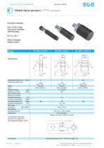
INDUCTIVE SENSORS Series IGVU Metal face sensors | PTFE-coated Proximity switches M12 / M18 / M30 One piece stainless steel housing DC 10...30 V Shock resistant Impact proof ID-No. Type Supply voltage [V] Switching current [mA] Short circuit proof Reverse protection Voltage drop max. [V] Current consumption [mA] Switching frequency [Hz] Ambient temperature [°C] EMC-class Protection [EN 60529] LED display Housing material Connection Operating distance sn Switching output PNP P31235 IGVU 05 GSP-C 10...30 DC 250 • • 1.5 5 180 – 25...+80 A IP 68 + IP 69 • AISI 316 L, PTFE-coated M12 connector Design...
Open the catalog to page 10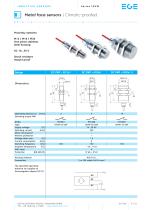
INDUCTIVE SENSORS Series IGVW Metal face sensors | Climatic-proofed Proximity switches M12 / M18 / M30 One piece stainless steel housing DC 10...30 V Shock resistant Impact proof Operating distance sn Switching output PNP ID-No. Type Supply voltage [V] Switching current [mA] Short circuit proof Reverse protection Voltage drop max. [V] Current consumption [mA] Switching frequency [Hz] Ambient temperature [°C] EMC-class Protection [EN 60529] Housing material Connection The specified operating distance (sn) applies to ferromagnetic objects (ST37). EGE-ELEKTRONIK SPEZIAL-SENSOREN GMBH TEL. +49 (0)4346...
Open the catalog to page 11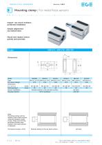
INDUCTIVE SENSORS Mounting clamp | For metal face sensors Impact- ans shock resistant, protected installation Simple adjustment via slotted holes Mount and replace sensor quickly and precisely ID-No. Type For sensor design Dimensions L1 x L2 x L3 Hole spacing e Sensor installation Housing material 34 x 24 x 40 40 x 30 x 40 55 x 40 x 40 20 26 40 flushed relative to the set back surface ST52, hardened Note: Mounting clamps are fastened to their metal surface using M6 hexagon socket screws. Make sure that the provided stainless steel washers have been placed in-between. The typical torque is 6 Nm....
Open the catalog to page 12All EGE-Elektronik Spezial-Sensoren GmbH catalogs and technical brochures
 About EGE - Overview
6 Pages
 Flow Sensors
120 Pages
 Accessories M12 Connector
10 Pages
 SDNC 500
2 Pages
 LDS 1000
2 Pages
 LDV 1000
2 Pages
 AGVU
AGVU1 Page
 SDN 550
1 Page
 SCS 440
1 Page
 KBM
KBM1 Page
 Serie cfc
1 Page
 series DN 752
1 Page
 series DGC 075
1 Page
 MFP
MFP1 Page
 TGBA
TGBA1 Page
 Serie AGVU
1 Page
 Serie HGVH
1 Page
 TGM 050 FW T1/T2
1 Page
 GK
GK104 Pages
 Serie IGEXHa
1 Page
 Dust / Gas Series IGEXHa
1 Page
 SDNC500
2 Pages
 SNS 552
2 Pages
 LDN 1000
2 Pages
 SDN 500
2 Pages
 Brochure Pressure-level
8 Pages
 Capacitive Sensors
29 Pages
 Opto high capacity systems
12 Pages
 Series MFP
1 Page
 Series LDN 1000
2 Pages
 Metal detectors
8 Pages
 Ultrasonic Sensors
9 Pages
 Infrared detectors
12 Pages
 Pressure/Level
8 Pages
 demanding environment
16 Pages



Archived catalogs
 Temperature Sensors
12 Pages
 Level Sensors
40 Pages

- Flowmeter
- Temperature probe
- Volume flow monitor
- Liquid flow monitor
- Level limit switch
- Pressure limiter
- Liquid level detector
- EGE level sensor
- Single-stage pressure regulator
- Stainless steel flow monitor
- EGE liquid level sensor
- Industrial pressure limiter
- EGE cylindrical proximity sensor
- Industrial flow monitor
- EGE inductive proximity sensor
- In-line flow meter
- Membrane regulator
- EGE signal amplifier
- Water flow monitor