Model S1
1 /5Pages

Model S1
1 /5Pages
Catalog excerpts

Model S1 - Pressure Reducing Valve with bellows Pressure Reducing Valve - Model S1 BASIC INFORMATION Type Operation Model Connections Ends Ratings Sizes Suitable for Self-operated pressure reducing valve with bellows Valve closes when outlet pressure increases S1 Flanged (DIN - ANSI) or Threaded (BSP - NPT) RF - RF, NPT, BSP PN25 - PN40 (150# - 300#) DN15 to DN200 [mm] (1/2” to 8”) Liquids, compressed air, neutral gases and steam Kv Cv Temperature Inlet max. pressure Outlet pressure 40 [barg] up to DN50 (2") 25 [barg] up to DN200 (8") 0,1 - 16 [barg] PARTS GALILEO 8, POL. IND. CAN ESTELLA 08635 REV. 01/ 14 ST ESTEVE SESROVIRES, BARCELONA, SPAIN www.efSVaIVeS.c°m This information is subjected to changes
Open the catalog to page 1
Model S1 - Pressure Reducing Valve with bellows GALILEO 8, POL. IND. CAN ESTELLA 08635 REV. 01/ 14 ST ESTEVE SESROVIRES, BARCELONA, SPAIN www-efsvalves-c°m This information is subjected to changes
Open the catalog to page 2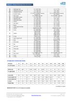
Model S1 - Pressure Reducing Valve with bellows IMPORTANT NOTE: Kv or CV reduced is available GALILEO 8, POL. IND. CAN ESTELLA 08635 REV. 01/ 14 ST ESTEVE SESROVIRES, BARCELONA, SPAIN www.efsvalves.c°ITI This information is subjected to changes
Open the catalog to page 3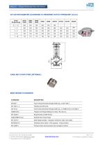
ACTUATOR DIAMETER ACCORDING TO REQUIRED OUTLET PRESSURE: D [mm] Outlet Range [barg] CAGE ANTI CAVITATION (OPTIONAL) MAIN DESIGN STANDARDS Face-to-face dimensions flanges drilled acc. to EN 1092-1 Flanges and their joints Face-to-face dimensions flanges drilled acc. to ASME B16.5 or EN 558-2 Flanges and Flanged Ratings for Class 150, 300, etc. Requirements for BSP thread National Pipe Thread Taper Shell design strength - Tabulation method for steel valve shells Industrial control valves - Flow capacity - Test procedure Pressure tests, test procedures and acceptance criteria GALILEO 8, POL. IND....
Open the catalog to page 4
Model S1 - Pressure Reducing Valve with bellows The medium flows through the valve body in the direction indicated by the arrow. The position of the valve plug determines the flow rate across the area released between the plug and seat. To control the pressure, the operating diaphragm is pretensioned by the positioning springs and the set point adjuster. As a result, the valve is opened by the force of the positioning springs in pressureless state (p1 = p2). The downstream pressure p2 to be controlled is tapped downstream of the valve and transmitted through the control line to the operating...
Open the catalog to page 5All EFSVALVES catalogs and technical brochures
 Model PRV30
4 Pages
 Model PRV44
4 Pages
 Model PRV45
5 Pages
 Model PRV54
3 Pages
 Model PRV55
4 Pages
 Model S2
5 Pages
 Model VD
4 Pages
 Model C1
12 Pages
 Model EFSASIN-V
5 Pages
 MODEL 1415LP
2 Pages
 MODEL 1415
4 Pages
 Model VFGJS
2 Pages
 Model FV/FFV
2 Pages