XDD 1 MKII/115/230 V and 24 V DC Diaphragm Pumps Instruction Manual
1 /38Pages

XDD 1 MKII/115/230 V and 24 V DC Diaphragm Pumps Instruction Manual
1 /38Pages
Catalog excerpts
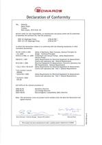
Manor Royal, declare under our sole responsibility, as manufacturer and person within the EU authorised to assemble the technical file, that the product(s) to which this declaration relates is in conformity with the following standard(s) or other normative document(s) EN ISO 12100-2: 2003 Safety of Machinery, Basic Concepts, General Principles for + A1:2009 Design. Technical Principles EN1012-2:1996, A1: 2009 Compressors and Vacuum Pumps. Safety Requirements. Vacuum Pumps EN61010-1: 2001 Safety Requirements for Electrical Equipment for Measurement, Control and Laboratory Use. General Requirements...
Open the catalog to page 2
For return of equipment, complete the HS Forms at the end of this manual. © Edwards Limited 2010. All rights reserved. Edwards and the Edwards logo are trademarks of Edwards Limited.
Open the catalog to page 3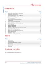
Figure Page Table Page Trademark credits Viton® is trademark of DuPont Dow Elastomers L.L.C. © Edwards Limited 2010. All rights reserved. Edwards and the Edwards logo are trademarks of Edwards Limited.
Open the catalog to page 4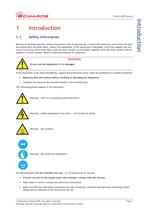
Remove all packing material, remove the product from its packing-box, remove the protective covers from the inlet and outlet ports and keep them, inspect the equipment. If the equipment is damaged, notify the supplier and the carrier in writing within three days; state the item number of the product together with the order number and the supplier's invoice number. Retain all packing material for inspection. If the equipment is not used immediately, replace the protective covers. Store the equipment in suitable conditions. • Read and obey this manual before installing or operating the equipment....
Open the catalog to page 5
• If the equipment is brought from cold environment into a room for operation, allow the equipment to warm Q up (pay attention to water condensation on cold surfaces). Q- • Make sure ventilation is adequate if pump is installed in a housing or if ambient temperature is elevated. ^ Obey all relevant safety requirements (regulations and guidelines) and adopt suitable safety measures. ¡_¡. • Provide a firm level platform for the equipment and check that the system to be evacuated is mechanically Q stable and that all fittings are secure. —' Note: Flexible elements tend to shrink when evacuated....
Open the catalog to page 6
Pumps with dual-voltage motor: The motor Is shut down by a thermal cutout In the winding. Q_ Manual reset is necessary. Switch off the pump or isolate the equipment from mains. Wait approx. five minutes before restarting the pump. Pumps with 24 V DC voltage: The motor is protected by a temperature sensor at the circuit board (current limitation if the temperature at the circuit board is higher than 70°C). Avoid high heat supply (e. g. due to hot process gases). Ensure sufficient air admittance if pump is installed in a housing. Due to the residual leak rate of the equipment, there may be an exchange...
Open the catalog to page 7
A746-02-885 Issue A Introduction Figure 1 - General view of XDD 1 with dual-voltage motor 1. 2. 3. 4. Page 4 Handle (removable) Inlet (small flange) NW16 Pump feet (adjustable) Voltage selector switch 5. 6. 7. 8. Fuse holder Mains switch Mains input Outlet (silencer) © Edwards Limited 2010. All rights reserved. Edwards and the Edwards logo are trademarks of Edwards Limited.
Open the catalog to page 8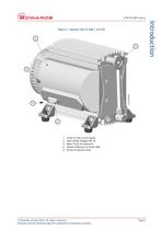
A746-02-885 Issue A Introduction Figure 2 - General view of XDD 1 24 V DC 1. 2. 3. 4. 5. Cover of the circuit board Inlet (small flange) NW 16 Male 15 pin D-connector Outlet (silencer) at lower side Screw to secure cover © Edwards Limited 2010. All rights reserved. Edwards and the Edwards logo are trademarks of Edwards Limited. Page 5
Open the catalog to page 9
This page has been intentionally left blank. © Edwards Limited 2010. All rights reserved. Edwards and the Edwards logo are trademarks of Edwards Limited.
Open the catalog to page 10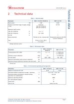
Table 1 - Electrical data Voltage selection switch Table 2 - Performance data Table 3 - Environmental operating and storage data © Edwards Limited 2010. All rights reserved. Edwards and the Edwards logo are trademarks of Edwards Limited.
Open the catalog to page 11
Table 4 - Mechanical data Table 5 - Materials data © Edwards Limited 2010. All rights reserved. Edwards and the Edwards logo are trademarks of Edwards Limited.
Open the catalog to page 12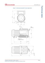
A746-02-885 Issue A Technical data Figure 3 - Dimensional drawing XDD 1 (dual-voltage motor) © Edwards Limited 2010. All rights reserved. Edwards and the Edwards logo are trademarks of Edwards Limited. Page 9
Open the catalog to page 13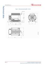
A746-02-885 Issue A Technical data Figure 4 - Dimensional drawing XDD 1 24 V DC Page 10 © Edwards Limited 2010. All rights reserved. Edwards and the Edwards logo are trademarks of Edwards Limited.
Open the catalog to page 14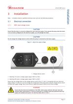
Note: A suitably trained or qualified technician must carry out the following procedures. Ensure that the motor is correctly configured for your electrical supply. If you operate the pump when the motor is not correctly configured for the electrical supply, you will damage the motor. Do not change the voltage selector switch while the pump is connected to the mains supply. Figure 5 - Adjust the supply voltage 1. Voltage selector switch 1. Selecting 115 covers a voltage supply range of 100 V to 120 V. 2. Selecting 230 covers a voltage supply range of 200 V to 240 V. Ensure that the voltage shown...
Open the catalog to page 15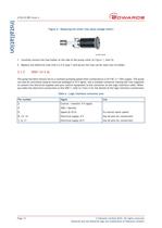
Figure 6 - Replacing the motor fuse (dual-voltage motor) 1. Carefully remove the fuse holder at the side of the pump (refer to Figure 1, item 5). 2. Replace the defective fuse with a 2.5 A type T and secure the fuse carrier back into its holder. The pump has been factory set to a constant pumping speed when connected to a 24 V DC (=/-10%) supply. The pump can also be controlled using an external analogue 0-10 V signal. Use a suitable connector mating half (not supplied) to connect the electrical supplies and your control equipment to the connector on the logic interface cable. When you make the...
Open the catalog to page 16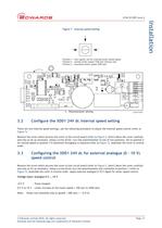
Figure 7 - Internal speed setting Position 1 - zero speed, set for external motor speed signal Position 2 - normal motor speed 1700 rpm (factory set) Position 3 - maximum motor speed 2200 rpm 1. Potentiometer setting dcs/ssiaoos 3.2 Configure the XDD1 24V dc internal speed setting There are two internal speed settings, use the following procedure to adjust the internal speed control (refer to Remove the screw which secures the cover to the circuit board (refer to Figure 2, itemi) Move the cover carefully and only as far as necessary. Using a screw driver, turn the potentiometer to one of two...
Open the catalog to page 17All EDWARDS catalogs and technical brochures
 SPEEDIVALVE
2 Pages
 GV
GV12 Pages
 XDD1
XDD12 Pages
 PGC
PGC2 Pages
 8200
82002 Pages
 IS 320FX
2 Pages
 RGA
RGA8 Pages
 EH
EH2 Pages
 RV
RV8 Pages
 nXDS
nXDS12 Pages
 XDS series
4 Pages
 EOSi ROTARY SCREW VACUUM PUMPS
12 Pages
 EDP CHEMICAL DRY VACUUM PUMP
4 Pages
 CXS CHEMICAL DRY VACUUM PUMPS
12 Pages
 CXS chemical dry vacuum pump
4 Pages
 EDC DRY CLAW VACUUM PUMPS
8 Pages
 gxs dry screw vacuum pumps
20 Pages
 nXLi DRY PUMPS
2 Pages
 XDD1 DIAPHRAGM VACUUM PUMP
2 Pages
 XDS35i DRY SCROLL PUMPS
4 Pages
 XDS DRY SCROLL PUMPS
4 Pages
 nXDS DRY SCROLL PUMPS
12 Pages
 T-STATION 85
2 Pages
 AIM
AIM2 Pages
 WRG
WRG2 Pages
 Active ion gauge (AIGX)
2 Pages
 ASG2
ASG22 Pages
 ELD500
8 Pages
 nEXT Turbo Pumps
12 Pages
 EXT Turbo Pumps
4 Pages
 IPUP2 Dry Pump
2 Pages
 iXL1000 Dry Pump
2 Pages
 iXH Dry Pumps HF
2 Pages
 iXH Dry Pumps
2 Pages
 iH Dry Pumps Product
12 Pages
 RV Acoustic Enclosures
2 Pages
 RV Pumps
8 Pages
 ES Rotary Vane Pumps
16 Pages
 Small EM Pumps
12 Pages
 MAXX Dry Systems
16 Pages
 BGV Gate Valve w/LOTO
4 Pages
 GXS Dry Pumps
20 Pages
 nXDS Acoustic Enclosures
2 Pages
 nXDS Accessories
32 Pages
 TiTan Ion Pumps
4 Pages
 EDP Pumps
4 Pages
 CXS Dry Pumps
12 Pages
 Edwards_Product_Catalogue
604 Pages
 nXDS Scroll Pumps
12 Pages
 EM18 Vacuum Pumps Datasheet
2 Pages
 ADC Datasheet
4 Pages
 Acoustic enclosures
2 Pages
 nEXT Brochure
12 Pages
 PRODUCT CATALOGUE 2012
470 Pages
 CXS Dry Pump
9 Pages
 EV Brochure
6 Pages
 Spectra G
4 Pages
 Atlas? Gas Abatement Systems
2 Pages
 GX Next Generation Dry Pumps
4 Pages
 iGX Dry Pumps
4 Pages
 iXL120 Dry Pump
2 Pages
 CG16K Capsule Dial Gauges
2 Pages
 T-Station 75
2 Pages
 EXT75-255DX
6 Pages
 XDS Dry Scroll Pump
6 Pages
 Barocel® 600 Datasheet
2 Pages
 Active Ion Gauge Datasheet
4 Pages
 Wide Range Gauge Datasheet
2 Pages
 APGX-H Datasheet
4 Pages
 APG100 Datasheet
2 Pages
 Vapour Booster Pumps
60 Pages
 RV ATEX Rotary Vane Pumps
34 Pages
 RV Rotary Vane Pumps
6 Pages
 XDS Scroll Pumps
2 Pages


Archived catalogs
 Mechanical Booster
12 Pages
 Liquid Ring Pumps
2 Pages
 Rotary vane datasheet
2 Pages
 Dry pump brochure
12 Pages
 D-Lab Diaphragm vacuum pump
4 Pages
 RV Rotary vane pump manual
58 Pages
 RV Brochure
6 Pages


- Valve
- Manual valve
- Stainless valve
- Air compressor
- Pneumatic valve
- EDWARDS vacuum generator
- Gas analyzer
- Flange valve
- On/off valve
- EDWARDS cooler
- ISO valve
- EDWARDS single-stage vacuum pump
- Gate valve
- EDWARDS liquid cooler
- Standard valve
- EDWARDS lubricated vacuum generator
- EDWARDS lubricated vacuum pump
- Process analyzer