nXDS Accessories
1 /32Pages

nXDS Accessories
1 /32Pages
Catalog excerpts

Instruction Manual nXDS Pump Accessories
Open the catalog to page 1
This page has been intentionally left blank.
Open the catalog to page 2
© Edwards Limited 2013. All rights reserved. Edwards and the Edwards logo are trademarks of Edwards Limited.
Open the catalog to page 3
© Edwards Limited 2013. All rights reserved. Edwards and the Edwards logo are trademarks of Edwards Limited.
Open the catalog to page 4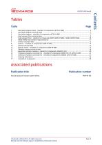
Associated publications Publication title Vacuum pump and vacuum system safety © Edwards Limited 2013. All rights reserved. Edwards and the Edwards logo are trademarks of Edwards Limited.
Open the catalog to page 5
This page has been intentionally left blank. © Edwards Limited 2013. All rights reserved. Edwards and the Edwards logo are trademarks of Edwards Limited.
Open the catalog to page 6
This manual provides installation, operation and maintenance instructions for the Edwards range of accessories for the nXDS pump range. The accessories are shown in Figure 1. The Item Numbers for the accessories are listed in the appropriate sections. The accessories must be used as specified in this manual. Read this manual before installing accessories onto the nXDS pump. Important safety information is highlighted as WARNING and CAUTION instructions; these instructions must be obeyed. The use of WARNINGS and CAUTIONS is defined below. WARNING Warnings are given where failure to observe the...
Open the catalog to page 7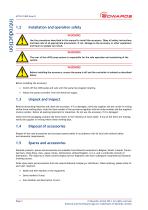
Installation and operation safety WARNING Use the procedures described in this manual to install the accessory. Obey all safety instructions and take note of all appropriate precautions. If not, damage to the accessory or other equipment and injury to people can result. WARNING The user of the nXDS pump system is responsible for the safe operation and monitoring of the system. WARNING Before installing the accessory, ensure the pump is off and the controller is isolated as described below. Before installing the accessory: Switch off the nXDS pump and wait until the pump has stopped rotating....
Open the catalog to page 8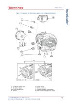
Figure 1 - Accessories for nXDS pumps - general view (o-ring seals not shown) 1. Gas ballast adaptor blank 2. Gas ballast adaptor 3a+b. Inlet/exhaust filter 4. Silencer Exhaust nozzle Vibration isolators Chemical resistance conversion kit Pump-to-controller cable (not shown) © Edwards Limited 2013. All rights reserved. Edwards and the Edwards logo are trademarks of Edwards Limited.
Open the catalog to page 9
This page has been intentionally left blank. © Edwards Limited 2013. All rights reserved. Edwards and the Edwards logo are trademarks of Edwards Limited.
Open the catalog to page 10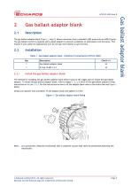
Gas ballast adaptor blank The gas ballast adaptor blank (Figure 1, item 1) allows conversion from a standard nXDS pump into an nXDS-R pump. The gas ballast control is replaced with a blank adaptor to prevent accidental air admittance into the pump. This feature is also useful for applications such as rare gas recirculation or gas recovery. Installation Table 1 - Gas ballast adaptor blank - checklist of components (A735-01-806) Qty Gas ballast adaptor blank O-ring 19.6ID X 2.4 Install the gas ballast adaptor blank The method for installing the gas ballast adaptor blank follows some of the stages...
Open the catalog to page 11
This page has been intentionally left blank. © Edwards Limited 2013. All rights reserved. Edwards and the Edwards logo are trademarks of Edwards Limited.
Open the catalog to page 12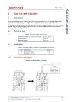
The gas ballast adaptor (Figure 1, item 2) fits in place of the gas ballast control. The gas ballast adaptor allows connection of a controlled supply of inert gas such as nitrogen into the low vacuum stage of the pump. The gas purge can be used to dilute flammable gases down to a safe level (Edwards recommends 1/4 of the Lower Explosive Limit). An inert purge can also be used to reduce the likelihood of gas vapours such as iodine from condensing at the outlet stage of the pump. Technical data Table 2 - Gas ballast adaptor technical data Maximum permitted gas ballast inlet pressure Orifice diameter...
Open the catalog to page 13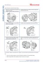
Ensure the pump is switched off before fitting. 1. Undo the 2 off retaining bolts and partially remove the fan cowl. Caution: Cooling fan supply lead attached. 2. Carefully disconnect the cooling fan electrical supply lead and remove the fan cowl. 3. Using a 21 mm AF spanner, remove the gas ballast control assembly. 4. Carefully remove the gas ballast control seat and O-ring. 5. Assemble the gas ballast adaptor and new O-ring, ensure the O-ring and seal surface are clean and free of dust or dirt. 6. Reconnect and assemble the cooling fan supply lead and fan cowl (1) in reverse order. Torque the...
Open the catalog to page 14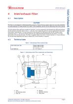
Inlet/exhaust filter Description CAUTION This filter is not designed to withstand positive pressures. Ensure that any system valves are correctly scheduled to avoid pumping to a closed exhaust line. Refer to the Installation section of the nXDS pump instruction manual. The inlet/exhaust filter performs a number of functions. It can be connected in-line between the nXDS pump exhaust and the exhaust extraction system (Figure 1, item 3a), this is especially useful for process applications such as gas recirculation. Alternatively, it can be connected in-line between the nXDS pump inlet and the chamber...
Open the catalog to page 15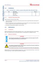
Inlet/exhaust filter Installation Table 5 - Inlet/exhaust filter - checklist of components NW25 (A505-97-805)/ NW40 (A505-97-806) Qty Filter assembly Centring ring Install the inlet/exhaust filter Ensure the pump is switched off before fitting. 1. Inspect the mating port and seals faces, ensure they are free of dirt or any particulate which could cause the vacuum seal to leak. 2. Place the centring ring in the end of the NW25 filter port and seat the filter onto the pump mating port. Ensure the filter is fitted in the correct orientation (refer to Figures 1 and 4). 3. Fit the NW25 retaining clamp...
Open the catalog to page 16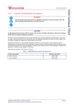
Inspection and replacement of the element WARNING Take all necessary precautions if toxic or dangerous substances have been pumped. Wear PPE when handling contaminated filters and filter elements. CAUTION At high temperature (in excess of 250 ºC) tip seal wear product will begin to decompose, giving rise to gaseous fumes which can produce unpleasant symptoms. The filter may be contaminated with the process chemicals that have been pumped during operation. Ensure that the pump is decontaminated before maintenance and that adequate precautions are taken to protect people from the effects of dangerous...
Open the catalog to page 17All EDWARDS catalogs and technical brochures
 SPEEDIVALVE
2 Pages
 GV
GV12 Pages
 XDD1
XDD12 Pages
 PGC
PGC2 Pages
 8200
82002 Pages
 IS 320FX
2 Pages
 RGA
RGA8 Pages
 EH
EH2 Pages
 RV
RV8 Pages
 nXDS
nXDS12 Pages
 XDS series
4 Pages
 EOSi ROTARY SCREW VACUUM PUMPS
12 Pages
 EDP CHEMICAL DRY VACUUM PUMP
4 Pages
 CXS CHEMICAL DRY VACUUM PUMPS
12 Pages
 CXS chemical dry vacuum pump
4 Pages
 EDC DRY CLAW VACUUM PUMPS
8 Pages
 gxs dry screw vacuum pumps
20 Pages
 nXLi DRY PUMPS
2 Pages
 XDD1 DIAPHRAGM VACUUM PUMP
2 Pages
 XDS35i DRY SCROLL PUMPS
4 Pages
 XDS DRY SCROLL PUMPS
4 Pages
 nXDS DRY SCROLL PUMPS
12 Pages
 T-STATION 85
2 Pages
 AIM
AIM2 Pages
 WRG
WRG2 Pages
 Active ion gauge (AIGX)
2 Pages
 ASG2
ASG22 Pages
 ELD500
8 Pages
 nEXT Turbo Pumps
12 Pages
 EXT Turbo Pumps
4 Pages
 IPUP2 Dry Pump
2 Pages
 iXL1000 Dry Pump
2 Pages
 iXH Dry Pumps HF
2 Pages
 iXH Dry Pumps
2 Pages
 iH Dry Pumps Product
12 Pages
 RV Acoustic Enclosures
2 Pages
 RV Pumps
8 Pages
 ES Rotary Vane Pumps
16 Pages
 Small EM Pumps
12 Pages
 MAXX Dry Systems
16 Pages
 BGV Gate Valve w/LOTO
4 Pages
 GXS Dry Pumps
20 Pages
 nXDS Acoustic Enclosures
2 Pages
 TiTan Ion Pumps
4 Pages
 EDP Pumps
4 Pages
 CXS Dry Pumps
12 Pages
 Edwards_Product_Catalogue
604 Pages
 nXDS Scroll Pumps
12 Pages
 EM18 Vacuum Pumps Datasheet
2 Pages
 ADC Datasheet
4 Pages
 Acoustic enclosures
2 Pages
 nEXT Brochure
12 Pages
 PRODUCT CATALOGUE 2012
470 Pages
 CXS Dry Pump
9 Pages
 EV Brochure
6 Pages
 Spectra G
4 Pages
 Atlas? Gas Abatement Systems
2 Pages
 GX Next Generation Dry Pumps
4 Pages
 iGX Dry Pumps
4 Pages
 iXL120 Dry Pump
2 Pages
 CG16K Capsule Dial Gauges
2 Pages
 T-Station 75
2 Pages
 EXT75-255DX
6 Pages
 XDS Dry Scroll Pump
6 Pages
 Barocel® 600 Datasheet
2 Pages
 Active Ion Gauge Datasheet
4 Pages
 Wide Range Gauge Datasheet
2 Pages
 APGX-H Datasheet
4 Pages
 APG100 Datasheet
2 Pages
 Vapour Booster Pumps
60 Pages
 RV ATEX Rotary Vane Pumps
34 Pages
 RV Rotary Vane Pumps
6 Pages
 XDS Scroll Pumps
2 Pages


Archived catalogs
 Mechanical Booster
12 Pages
 Liquid Ring Pumps
2 Pages
 Rotary vane datasheet
2 Pages
 Dry pump brochure
12 Pages
 D-Lab Diaphragm vacuum pump
4 Pages
 RV Rotary vane pump manual
58 Pages
 RV Brochure
6 Pages


- Manual valve
- Stainless valve
- Compressor stage
- Air compressor
- Pneumatic valve
- EDWARDS vacuum generator
- Gas analyzer
- Flange valve
- On/off valve
- EDWARDS cooler
- ISO valve
- Single-stage vacuum pump
- Gate valve
- EDWARDS liquid cooler
- Standard valve
- EDWARDS lubricated vacuum generator
- EDWARDS lubricated vacuum pump
- Process analyzer