- Catalogs
- Ecostar Burners
- MONOBLOCK GAS BURNERS
MONOBLOCK GAS BURNERS
1 /39Pages

MONOBLOCK GAS BURNERS
1 /39Pages
Catalog excerpts

ecostar COMBUSTION SYSTEMS MONOBLOCK GAS BURNERS INSTALLATION, OPERATING AND MAINTENANCE MANUAL ONE-STAGE, TWO-STAGE AND MODULATING OPERATION
Open the catalog to page 1
DEAR USER, ECOSTAR ECO 1, ECO 2, ECO 30, ECO 45 GAS burners are prepared and manufactured according to the latest technical developments and safety rules. It is easy to use for our customers. We recommend that you read this manual and safety warnings thoroughly before the use of the device in order to ensure safe, cost effective and environmental-friendly use. If you encounter any issue that is not explained clearly in this manual or you could not understand, please contact with our service department. We thank you for choosing ECOSTAR brand. Ecostar Gas Burners are manufactured in accordance...
Open the catalog to page 2
WARNINGS Warning Symbols and Descriptions
Open the catalog to page 4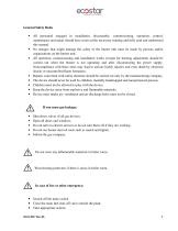
General Safety Rules • All personnel engaged in installation, disassembly, commissioning, operation, control, maintenance and repair should have received the necessary training and fully read and understood this manual. • No changes that might damage the safety of the burner unit must be made by persons and/or organizations on the burner unit. • All operation, commissioning and installation works (except for burning adjustment) should be carried out when the burner is not operating and after disconnecting the power supply. Noncompliance with these rules may lead to serious bodily injuries and...
Open the catalog to page 5
The burner installation must be carried out in accordance with the instructions. Vibration can damage the burner and its components. Keep boiler doors closed while starting burner and during burner operation. Check combustion values to be correct by using flue gas analyzer at the whole adjustment range between minimum, full load, and ignition load. Use lifting device or belt for lifting fan motor, if necessary During the first commissioning of the burner or in case of any revision carried out in the electrical system or motor cables by any reason, direction of the fan rotation must certainly...
Open the catalog to page 6
TERMS OF WARRANTY Main and auxiliary equipment and all components used in Ecostar gas burners are guaranteed for 1 year by TERMO ISI SİST. A.Ş starting from the date of commissioning under the maintenance, adjustment, operating conditions and relevant mechanic, chemical and thermal effects explained herein. Please note that this warranty is only valid if the device(s) is commissioned and maintained by our authorized services. Our company reserves the right to make any modifications on the product and all instructions thereof for improvement purposes. Out of Warranty Conditions • Any damage arising...
Open the catalog to page 7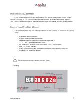
BURNER’S GENERAL FEATURES ECOSTAR gas burners are manufactured such that they operate in gas pressure of min. 20 mbar and max. 300 mbar., at 15%...+10% of nominal voltage, between the ambient temperature range of 15ºC….+60˚C and declared capacity and boiler pressure ranges with Natural Gas and Liquid Petrol Gas. Purpose of Use and Work Limits of Burners • This product works at any load value equivalent to its max. capacity or covered by its capacity range; - In hot water and steam boilers, In direct and indirect hot air generators, Industrial appliances operating at temperature below 600 0C,...
Open the catalog to page 8
TECHNICAL DATA Capacity Table GAS BURNERS CAPACITY TABLE
Open the catalog to page 12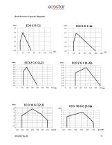
Back Pressure-Capacity Diagrams
Open the catalog to page 13
Burner Dimensions
Open the catalog to page 15
Gas Hood Pressure Loss Diagram Gas hood pressure loss measurements are conducted in atmospheric pressure. Consider the below data while conducting measurement in counter pressure boilers. Pm: Gas hood pressure while burner is connected to the boiler and working PF: Combustion chamber pressure PBr: Burner net gas hood pressure PBr = Pm - PF
Open the catalog to page 16
Flame Length and Diameter Noise Level Product operates within the range of 75 decibels max. and 85 decibels. BURNER HANDLING INFORMATION • Lift the product by holding the handles as seen in the picture. • Prevent strong impacts on top of the product and vibration while handling the product. • Do not leave the product in wet environment. 02.01.2017 Rev.06
Open the catalog to page 18
Dimensions of the box used for handling
Open the catalog to page 19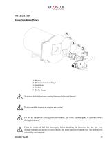
INSTALLATION Burner Installation Picture 1- Burner 2- Burner connection flange 3- Drift Bolts 4- Gasket 5- Boiler flange You must definitely ensure sealing between boiler and burner! Device must be shipped in original packaging! Do not lift the device holding from servomotor, gas valve, impulse pipes or pressure switch during installation! Clean the inside of fuel line thoroughly before installing the burner to the fuel line. Any damage that may occur due to solid objects and metal particles from the fuel line shall not be covered by our company. 02.01.2017 Rev.06
Open the catalog to page 20
While installing the burner in reverse flame front mirror boilers, flame tube tip must be adjusted such that it gets inside by 50 mm-100 mm from flue pipes (50mm≤A≤100mm). Otherwise flue gas temperature will rise and fuel consumption will increase. COMMISSIONING Before Commissioning Ignition and Ionizasyon System Electrical Connection Perform electrical connections according to the diagram provided with the burner. Follow general security rules during installation of electric wiring and making connections. Connect the earthing terminal in electric panel to the earthing installation. 02.01.2017...
Open the catalog to page 21
General Controls Make sure to perform the following controls before commissioning the burner. • Are the electrical connections correct? • Is there electricity current? • Is there gas? • Has the heating system been filled with water? • Is the thermostat set at the required temperature? • Has the boiler explosion lid been controlled? • Is there sufficient air in boiler room (ventilation section cm2 = boiler capacity kW x 7) • Has the boiler been installed correctly? Has the boiler cover been closed properly? • Has the air of the gas line been removed? Has a sealing test been made? Operation of...
Open the catalog to page 22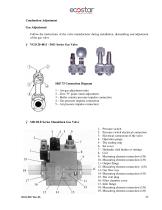
Combustion Adjustment Gas Adjustment Follow the instructions of the valve manufacturer during installation, dismantling and adjustment of the gas valve Ø VGD 20 4011 - 5011 Series Gas Valve SKP 75 Connection Diagram 1 – Air-gas adjustment ratio 2 – Zero "0" point (start) adjustment 3 – Boiler counter pressure impulse connection 4 – Gas pressure impulse connection 5 – Air pressure impulse connection Ø MB DLE Series Monoblock Gas Valve 1- Pressure switch 2- Pressure switch electrical connection 3- Electrical connection of the valve 4- Operation gauge 5- The sealing ring 6- Set cover 7- Hydraulic...
Open the catalog to page 23All Ecostar Burners catalogs and technical brochures
 DUCT BURNERS
22 Pages
 ECODENSE WT series
43 Pages
 FPB series
34 Pages
 SHG series
23 Pages
 Process burners 2017
12 Pages
 grm series burners 2017
8 Pages
 Duct burners 2017
4 Pages
 Monoblock Burners 2017
108 Pages
 Fuel-Oil Burners
8 Pages
 Hot Air Generato
2 Pages
 Dual Burners
8 Pages
 brulorler-ecostar-gaz
8 Pages
 Technical Catalogue
288 Pages
 CIB DIB DSE MIB for Industry
20 Pages
 Filtering,Pumping,Heating
2 Pages
 INDUSTRIAL BURNERS
2 Pages
 Gazoram Drying Burners
8 Pages
 Portable Heaters
6 Pages
 Diesel Burners
8 Pages
 2013 Company
19 Pages
 GAS PROCESS BURNERS
8 Pages
 light oil burner
8 Pages
 HEAVY OIL BURNER
8 Pages
 DUAL FUEL MONOBLOCK BURNER
8 Pages
 INDUSTRIAL BURNERS
8 Pages


Archived catalogs
 ECOSTAR Duct Burners
1 Page


- Direct fired burner
- Superheated water boiler
- Gas boiler
- Natural gas burner
- Pumping system
- Industrial pump unit
- Nozzle mix burner
- Stationary pump unit
- Indirect fired burner
- Self-priming pumping system
- Heating burner
- Fuel oil burner
- Management system
- Stationary hot air generator
- Boiler burner
- Compact boiler
- Gas hot air generator
- Standard burner