- Catalogs
- Ecostar Burners
- DUCT BURNERS
DUCT BURNERS
1 /22Pages

DUCT BURNERS
1 /22Pages
Catalog excerpts
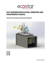
ecostar COMBUSTION SYSTEMS DUCT BURNERS INSTALLATION, OPERATING AND MAINTENANCE MANUAL ONE-STAGE, TWO-STAGE AND MODULATING OPERATION
Open the catalog to page 1
DEAR USER, ECOSTAR AH 100, AH 200, AH 300, duct burners are prepared and manufactured according to the latest technical developments and safety rules. It is easy to use for our customers. We recommend that you read this manual and safety warnings thoroughly before the use of the device in order to ensure safe, cost effective and environmental-friendly use. If you encounter any issue that is not explained clearly in this manual or you could not understand, please contact with our service department. We thank you for choosing ECOSTAR brand. This Operating Manual is an integral part of the burner...
Open the catalog to page 2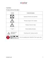
WARNINGS Warning Symbols and Descriptions
Open the catalog to page 4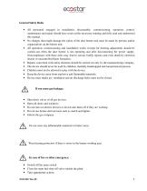
General Safety Rules • All personnel engaged in installation, disassembly, commissioning, operation, control, maintenance and repair should have received the necessary training and fully read and understood this manual. • No changes that might damage the safety of the duct burner unit must be made by persons and/or organizations on the burner unit. • All operation, commissioning and installation works (except for burning adjustment) should be carried out when the duct burner is not operating and after disconnecting the power supply. Noncompliance with these rules may lead to serious bodily injuries...
Open the catalog to page 5
The duct burner installation must be carried out in accordance with the instructions. Vibration can damage the burner and its components. Keep duct flanges and manholes closed while starting burner and during burner operation. During the first commissioning of the burner or in case of any revision carried out in the electrical system or motor cables by any reason, direction of the fan rotation must certainly be checked by the authorized technical service.
Open the catalog to page 6
TERMS OF WARRANTY Main and auxiliary equipment and all components used in Ecostar Duct Burners are guaranteed for 1 year by TERMO ISI SİST. A.Ş starting from the date of commissioning under the maintenance, adjustment, operating conditions and relevant mechanic, chemical and thermal effects explained herein. Please note that this warranty is only valid if the device(s) is commissioned and maintained by our authorized services. Our company reserves the right to make any modifications on the product and all instructions thereof for improvement purposes. Out of Warranty Conditions • Any damage arising...
Open the catalog to page 7
BURNER’S GENERAL FEATURES ECOSTAR process duct burners are designed to operate with natural gas and liquid petroleum gas at the declared capacity and pressure ranges to produce hot air. The gas collector of the duct burner provides fuel to the center of the diffuser, the emissions and the combustion efficiency can be controlled by optimum air-fuel mixture. Purpose of Use and Work Limits of the Burners This product works at any load value equivalent to its max. capacity or covered by its capacity range; -15 0C…+60 0C ambient temperature range, In industrial applications; Ovens, driers, smoke incinerators,...
Open the catalog to page 8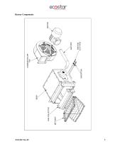
Burner Components
Open the catalog to page 9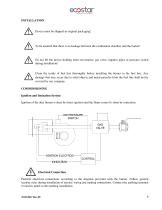
Device must be shipped in original packaging! To be ensured that there is no leakage between the combustion chamber and the burner! Do not lift the device holding from servomotor, gas valve, impulse pipes or pressure switch during installation! Clean the inside of fuel line thoroughly before installing the burner to the fuel line. Any damage that may occur due to solid objects and metal particles from the fuel line shall not be covered by our company. COMMISSIONING Ignition and Ionization System Ignition of the duct burner is done by direct ignition and the flame control is done by ionization....
Open the catalog to page 10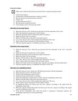
General Controls Make sure to perform the following controls before commissioning the burner. • Is there heat request? • Is thermostats and thermoelemans working correctly? • Has the electrical connections been correctly? • Is there gas? • Is there sufficient air flow? • Has the burner mounted correctly? • Is the leakage control of the gas line made? Operation of one-stage burner • Open the main gas valve; check the gas pressure from the manometer at the valve. • Check the thermostat and pressure switch settings. • Bring the operating switch on the burner panel to position 1. • Burner fan motor...
Open the catalog to page 11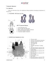
Combustion Adjustment Gas Adjustment Follow the instructions of the valve manufacturer during installation, dismantling and adjustment of the gas valve Ø VGD 20 4011 - 5011 Series Gas Valve SKP 75 Connection Diagram 1 – Air-gas adjustment ratio 2 – Zero "0" point (start) adjustment 3 – Boiler counter pressure impulse connection 4 – Gas pressure impulse connection 5 – Air pressure impulse connection Ø MB DLE Series Monoblock Gas Valve 1- Pressure switch 2- Pressure switch electrical connection 3- Electrical connection of the valve 4- Operation gauge 5- The sealing ring 6- Set cover 7- Hydraulic...
Open the catalog to page 12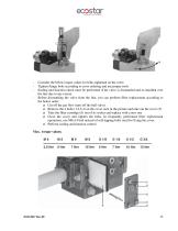
- Consider the below torque values for bolts tightened on the valve. - Tighten flange bolts according to cross ordering and use proper tools. - Sealing and function check must be performed if the valve is dismantled and re-installed over the line due to any reason. - Before dismantling the valve from the line, you can perform filter replacement according to the below order. o Cut off the gas flow (turn off the ball valve) o Remove the 4 bolts (1,2,3,4) on the cover seen in the picture and take out the cover (5). o Take the filter cartridge (6) out of its socket and replace with a new one o Close...
Open the catalog to page 13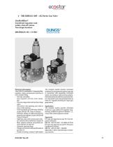
• MB ZRD(LE) 405 - 412 Series Gas Valve DUNGS® Combustion Controls GasMultiBloc® Combined regulator and safety shut-off valves Two-stage function MB-ZRD(LE) 405 - 412 B01 Technical description The DUNGS GasMultiBloc* integrates filter, regulator, valves and pressure switches in one compact fitting. - Dirt trap: microfilter - One regulator and two main vafves: B01 - One one-stage valve an d one two- stage valve - One valve is fast opening, one valve is slow or fast opening - Sol eno id va Ives up to 360 mbar (36 kPal as per DIN EN 161 Class A Group 2 - Sensitive setting of output pressure by proportional...
Open the catalog to page 14All Ecostar Burners catalogs and technical brochures
 MONOBLOCK GAS BURNERS
39 Pages
 ECODENSE WT series
43 Pages
 FPB series
34 Pages
 SHG series
23 Pages
 Process burners 2017
12 Pages
 grm series burners 2017
8 Pages
 Duct burners 2017
4 Pages
 Monoblock Burners 2017
108 Pages
 Fuel-Oil Burners
8 Pages
 Hot Air Generato
2 Pages
 Dual Burners
8 Pages
 brulorler-ecostar-gaz
8 Pages
 Technical Catalogue
288 Pages
 CIB DIB DSE MIB for Industry
20 Pages
 Filtering,Pumping,Heating
2 Pages
 INDUSTRIAL BURNERS
2 Pages
 Gazoram Drying Burners
8 Pages
 Portable Heaters
6 Pages
 Diesel Burners
8 Pages
 2013 Company
19 Pages
 GAS PROCESS BURNERS
8 Pages
 light oil burner
8 Pages
 HEAVY OIL BURNER
8 Pages
 DUAL FUEL MONOBLOCK BURNER
8 Pages
 INDUSTRIAL BURNERS
8 Pages


Archived catalogs
 ECOSTAR Duct Burners
1 Page


- Gas burner
- Direct fired burner
- Superheated water boiler
- Gas boiler
- Natural gas burner
- Pumping system
- Industrial pump unit
- Nozzle mix burner
- Stationary pump unit
- Indirect fired burner
- Self-priming pumping system
- Hot air generator
- Heating burner
- Fuel oil burner
- Compact boiler
- Boiler burner
- Management system
- Low-emission burner
- Stationary hot air generator
- Natural gas boiler