Catalog excerpts

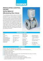
The modulating control valves of the newly conceived MDV-D1 series are built according to the EN 161 norms to be used on industrial combustion systems. They are particularly suitable for the proportional regulation of all combustion gas flows of the first, second and third family and of air. The electric motor is unipolar and bidirectional, with high static and maintaining torque for 3- position-control, or proportional with analogic input control signal: current or voltage change. The exact linear rating is achieved by means of particular, patented shutter disks, rotating on the same axis. Six different orifice sizes are available according to the operating conditions. MODULATING CONTROL VALVES Series MDV-D1 (Modulating Disc Valve) Electric gear motor separated from the gas flow Sturdy, compact construction, especially suitable for industrial applications Installation in any position Mechanical position indicator Adjustable rotation angle Manual/automatic operation and service switch Open/Stop/Closed with relay for cut phase Wide range of accessories on request: 1 or 2 potentiometers ranging from 150 ohm to 2,5 kohm 2 adjustable auxiliary microswitches with free electric contacts input control signal: 4÷20 mA or 0÷10 Vdc (Supply voltage 24Vac/50-60Hz) auxiliary shaft with 8 mm ø or with 9,5 mm square shaft Construction Group Control device Ambient temperature Opening/closing time Operating pressure Flanged connections Rating feature Control ratio : die-cast aluminium : 2 : without zero setting : -10 ÷ +60 °C : 30 s or 60 s / 90° : max. 1 bar : ISO 7500 - PN 16 : linear : 25:1 Base and cover Supply voltage on request Nominal load Enclosure Duty cycle Trip and auxiliary switch rating Potentiometer/s Cable gland Input signal : die-cast aluminium : 230 Vac / 50-60 Hz : 115 Vac / 50-60 Hz o 24 Vac / 50-60 Hz : 7 VA : IP 54 secondo IEC 529 : continuous 100% : 5 (1) A/250 Vac : 150; 1000; 2500 Ù : 2 x Pg 13,5 : 4 ÷ 20 mA o 0 ÷ 10 Vcc TECHNICAL DATA FEATURES Valve Gear motor
Open the catalog to page 1
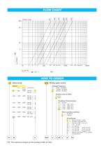
100 50 5 1 56 VN [m3/h] ÄP [mbar] 100 150 200 250 330 10 20 30 40 50 100 200 300 400 500 1000 2000 3000 4000 5000 10000 dv = 1 D1 56 P AR2 C 3 25 2 S 10 F4 FLOW CHART HOW TO ORDER P.S. The maximum torque on the auxiliary shaft is 3 Nm. D1 Valve body AR2 Rotary gear motor Orifice Voltage/Frequency mm 2 max P. Flange diam. A = 24Vac / 50-60Hz (mbar) B = 115Vac / 50-60Hz 56 = 560 1000 DN 50 = P C = 230Vac / 50-60Hz DN 65 = Q Rotation time at 50Hz 100= 1009 1000 DN 50 = P 2 = 30 s DN 65 = Q 3 = 60 s DN 80 = R Feedback Potentiometer 150= 1485 1000 DN 65 = Q 00 = No Pot DN 80 = R 11 = 1 Pot. 150...
Open the catalog to page 2
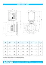
Econex s.r.l. - Via F. De Sanctis, 53 - I-20141 Milano Tel. +39 0289502912 - Fax +39 028463084 - www.econex.it - E-mail: info@econex.it 16 16 16 16 125 145 160 180 50 65 80 100 B C D L 18 18 20 20 102 122 138 158 165 185 200 220 191 191 203 229 4 4 8 8 7,5 8 9 11 A T.Amb, °C Pot, Ohm V Hz Load VA Time Sec Serial N Holding torque Nm Nominal torque Nm ° Type D L B C 168 9 152 288 120 50 115 168 142 58 84 DN 3 70 Ø8 A 7 Code: Type: amb.Temp: P max : Serial N°: Year: Kvs: Seat mm2 -10 to +60 bar Group: °C 2 MDV DN PN All reported data are subject to be changed without notice. DIMENSIONS (mm)...
Open the catalog to page 4All ECONEX S.R.L. catalogs and technical brochures
-
Air Pressure Switches
4 Pages
-
GAS FILTER Series FF - HF
4 Pages
Archived catalogs
-
Ball valves
2 Pages
-
pressure gauge
2 Pages
-
GMM
2 Pages
-
GDH
4 Pages
-
MRVB
4 Pages
-
SVS
4 Pages
-
SVB
4 Pages
-
BSV
4 Pages
-
AB1 series
4 Pages


