- Catalogs
- EBRO ARMATUREN Gebr. Bröer GmbH
- DOUBLE CHECK VALVE DC
DOUBLE CHECK VALVE DC
1 /2Pages

DOUBLE CHECK VALVE DC
1 /2Pages
Catalog excerpts
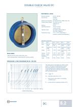
DOUBLE CHECK VALVE DC TECHNICAL DATA Nominal diameter: Face-to-face: ISO 5752 Flange accommodation: EN 1092 PN10/16, ASME Class 150 Flange Surface Design: EN 1092 Form A/B Marking: Operating pressure: Tightness check: Temperature range: ASME RF, FF EN 19 16 bar ≤ DN 250 10 bar ≥ DN 300 EN 12266 (Leakage Rate A) ISO 5208, Category 3 0°C to +130°C (depending on pressure, medium and temperature) Bearing operating - Can be disassembled, material-specific recycling possible - Maintenance-free wafer double check valve PRESSURE LOSS DIAGRAM DN 50 - DN 300 The values given in the diagram are valid for water at 20°C. They result of measurements at valves which are mounted in a horizontal conduction. For the ascertainment of pressure losses for other media, the water flow amount has to be calculated with the following formular: Wäp = √ YB x QB 1000 Wäp = equivalent water flow in m³/h YB = flow amount of the media in its operating conditions kg/m³ QB = volume of flow in operating condition (m³/h)
Open the catalog to page 1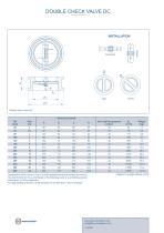
DOUBLE CHECK VALVE DC Installing the check valve on top of a pump please ensure that neither the valve is mounted directly on the pump flange or the following bend or a smoothing section of less than 5 x DN is observed. For tight sealing of the DC a back pressure of not less than 1 bar is required. Subject to change without notic
Open the catalog to page 2All EBRO ARMATUREN Gebr. Bröer GmbH catalogs and technical brochures
 PRODUCT OVERVIEW
8 Pages
 WATER- AND WASTEWATER TECHNOLOGY
12 Pages
 PNEUMATIC ACTUATOR SC
4 Pages
 CYCLE LOCK SYSTEM SOLUTION
4 Pages
 KNIFE GATE VALVE MV
9 Pages
 KNIFE GATE VALVE WB 11
8 Pages
 KNIFE GATE VALVE WB 12
7 Pages
 KNIFE GATE VALVE WB14
8 Pages
 KNIFE GATE VALVE XV
9 Pages
 SWITCH BOX SBU
3 Pages
 MANUAL OPERATION
2 Pages
 BUTTERFLY VALVE Q 011
4 Pages
 IMPELLER VALVE FS-M
2 Pages
 THROTTLE VALVE CK-M
2 Pages
 BUTTERFLY VALVE CK
2 Pages
 PLASTIC BUTTERFLY K 016
2 Pages
 CONTAINER VALVE BE 50/BE 80
2 Pages
 INFLATABLE SEAT INFLAS
4 Pages
 WAFER TYPE CHECK VALVE RSK
4 Pages
 PINCH VALVE QV
2 Pages
 F 012-DE
4 Pages
 HP 111-E
4 Pages
 K016
K0162 Pages
 CYCLE LOCK
4 Pages


- Lumibird manual valve
- Lumibird control valve
- Lumibird stainless steel valve
- Lumibird water valve
- Lumibird pneumatic valve
- Lumibird actuator
- Lumibird threaded valve
- Lumibird regulating valve
- Lumibird flange valve
- Lumibird shut-off valve
- Lumibird linear actuator
- Lumibird lever valve
- Lumibird electric valve
- Lumibird digital I/O
- Lumibird gas valve
- Lumibird I/O module
- Lumibird valve with handwheel
- Lumibird pneumatically-operated valve
- Lumibird butterfly valve