Group: EATON

Catalog excerpts

Push Pull Connectors High Performance Connection Technology
Open the catalog to page 1
Push-Pull connectors Introduction This catalogue presents the push-pull connectors ranges for industrial applications. These products are particularly suitable for high reliability and high quality applications where a simple yet fast method to connect/disconnect is required. Also suitable for high endurance and ease of operation in very limited spaces. The aesthetics of the product allows for perfect integration on front panel equipments. SOURIAU offers 3 main series of metallic circular connectors : • JBX series : basic push-pull series for signal transmission
Open the catalog to page 2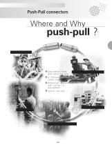
Push-Pull connectors l Extremely fast and easy to use l A thousand matings/ unmatings. l Enhanced appearance to add value to equipment l Space saving
Open the catalog to page 3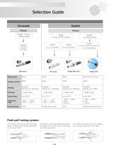
Selection Guide Unsealed Solder, Crimp or PCB contacts Solder, crimp or PCB contacts Shell material Insulator material Current rating Temperature range Protection index Push-pull locking system The locking of the plug into the receptacle is achieved by a simple axial push on the outer shell. Connection cannot be broken by pulling the cable or any other parts of the plug than the outer shell. To unmate the plug from the receptacle, just pull axially the outer shell.
Open the catalog to page 4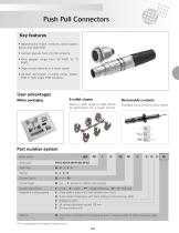
Push Pull Connectors Key features • Mechanically keyed : ensures correct polarisation and alignment. • Contact layouts from 2 to 30 contacts. • Wire gauges range from 30 AWG to 12 AWG. • High contact density in a small space. • Contact termination in either crimp, solder, PCB or right angle PCB contacts. User advantages 6-collet cluster Removable contacts Allows a wide range of cable diameter applications for a single connec- Blister packaging Available crimp versions allow easier Part number system JBX Basic series Shell type Contact type Contact termination Contact layout Shell size C :...
Open the catalog to page 5
Push Pull Connectors Shell types ER : fixed receptacle, front panel mounting, fixed front flange EA : fixed receptacle, back or front panel mounting, double nuts fixing (appropriate with 90° contacts for PCB) EP : fixed receptacle, back panel mounting, fixed rear panel flange (appropriate with 90° contacts for PCB) FD : straight plug with cable clamping ED : fixed receptacle, protuding shell, fixed front flange SR : fixed receptacle with cable clamping, front panel mounting, fixed front flange FC : 90° elbow plug with cable clamping PC : cable mounted receptacle
Open the catalog to page 6
Push Pull Connectors Dimensions ER : Fixed receptacle, front panel mounting EP : Fixed receptacle, back panel mounting PC : Cable mounted receptacle
Open the catalog to page 7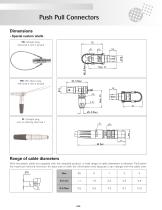
Push Pull Connectors • Special custom shells shell size 0 with a lanyard shell size 0 with a lanyard with no latching shell size 1
Open the catalog to page 8
Push Pull Connectors • Keying angles JBX Series are mechanically keyed to ensure correct alignment of the inserts before the contacts mate. «G» : normal inserts ; 0° keying angle, plugs with pin contacts, receptacles with socket contacts «J» : reversed gender inserts ; twin narrow keys, plugs with socket contacts, receptacles with pin contacts.
Open the catalog to page 9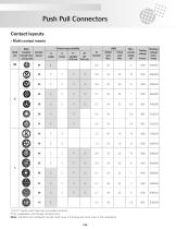
Push Pull Connectors Contact layouts • Multi contact inserts Shell size Male insulator Contact viewed from layout wiring side Contact types available Crimp wire Solder wire Working voltage (Vdc / Vrms) Testing voltage Inserts with fixed non removable contacts * For receptacles with female contacts only. Note : Contacts are numbered counter clock wise in the plug and clock wise in the receptacle. 208
Open the catalog to page 10
Push Pull Connectors Contact layouts Male Shell insulator Contact size viewed from layout Contact types available Solder wire Crimp wire Testing voltage Inserts with fixed non removable contacts * For receptacles with female contacts. Note : Contacts are numbered counter clock wise in the plug and clock wise in the receptacle. 209
Open the catalog to page 11
Push Pull Connectors Contact layouts • Multi contact inserts Male Shell insulator Contact size viewed from layout Contact types available Solder wire Crimp wire Testing voltage Inserts with fixed non removable contacts * For receptacles with female contacts. Note : Contacts are numbered counter clock wise in the plug and clock wise in the receptacle. • Voltage Test Procedure - The testing voltage corresponds to the maximum voltage the connector is able to withstand in normal climatic conditions. The value is about 75% of the electrical breakdown voltage. The testing voltage level can be...
Open the catalog to page 12
Push Pull Connectors Options • Protective boot Dimensions Part number Shell size * Color code / In size 00, available only in black Material : Color code Parts that require a protective boot need to be ordered with an M suffix. Protective boots are With each JBX connector, one protective boot can accept diverse cable diameters thus the end-user can manage various cable diameters without bothering with multiple part numbers. • Caps : an efficient protection against dust Part number
Open the catalog to page 13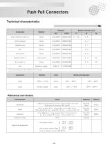
Push Pull Connectors Technical characteristics Component Outer shell and collet nut Latching sleeve Shielding ring Half bushes Beryllium copper (1) Gold thickness as per MIL-G-45204C type 1, class 00. Working Temperature • Mechanical and climatics Characteristics > 1000 cycles (except for 0.7 mm crimp contacts for which endurance is limited to 500 cycles) 50 g, duration 6 ms ; contact Ø 0.7 mm and 0.9 mm 100 g, duration 6 ms ; contact Ø 1.3 mm - 1.6 mm and 2 mm Protection index - 55°C + 200°C - 67°F + 392°F (only on request, consult SOURIAU) with plastic collets Operating temperature with...
Open the catalog to page 14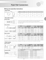
Push Pull Connectors Wiring and assembly instructions • Panel cutout Size • Removable contacts Reliable design • Conical entry with chamfered edge on the socket contact and smooth slope on the pin contact ensure perfect concentric mating even when handled carelessly. • The pressure spring of the socket contact maintains a constant force on the pin contact when mated. Crimp contacts Contact ØC Usable cables Core section (mm2) Solder contacts Usable cables Core section (mm2) Max. Contact Endurance current resistance (number rating (A) (m?) of cycles) 7 10 15 17 30 Max. Contact Endurance...
Open the catalog to page 15All EATON catalogs and technical brochures
-
 High Power Solutions
36 Pages
-
 ARINC 600 Backshell
2 Pages
-
 J15 & J17 Series
2 Pages
-
 8D Series Composite
9 Pages
-
 RoHS STATUS
22 Pages
-
 Hermetic Connectors
68 Pages
-
 Bulkhead Feedthrough Solutions
48 Pages
-
 Overmoulded Cable assemblies
8 Pages
-
 Non-magnetic D-Sub Connectors
53 Pages
-
 Backshells and Conduits
8 Pages
-
 Catalog UTV series
19 Pages
-
 Catalog UTP
24 Pages
-
 Catalog Clipper
28 Pages
-
 Catalog MSO series
5 Pages
-
 Catalog MSM series
5 Pages
-
 Catalog MB series
2 Pages
-
 Catalog MSG Series
6 Pages
-
 Catalog SMS IP series
8 Pages
-
 UTL catalog
80 Pages
-
 SMS Quick Mating
23 Pages
-
 ELIO® Fiber Optic Technology
44 Pages


