
- Catalogs
- Eaton Hydraulics
- Eaton Torque Limiting Coupling Installation, Operation and Maintenance Manual Airflex® Product Line


- Products
- Catalogs
- News & Trends
- Exhibitions
Eaton Torque Limiting Coupling Installation, Operation and Maintenance Manual Airflex® Product Line

Eaton Torque Limiting Coupling Installation, Operation and Maintenance Manual Airflex® Product Line
This manual provides essential guidelines for the installation, operation, and maintenance of the Eaton Airflex Torque Limiting Coupling (TLC). It stresses the importance of using genuine Airflex parts to ensure optimal performance and maintain warranty validity. Contact information for support is available for both U.S. and international customers.
The manual emphasizes adhering to hazard warnings to prevent injury or equipment damage. The Airflex TLC is designed for torque limiting applications in grinding mills, protecting against torque spikes by disengaging the mill from the motor when excessive torque is detected. It uses non-asbestos friction material and comes in various sizes.
The TLC operates by inflating an air actuating tube, pressing friction shoe assemblies against a drum attached to the driven component, allowing torque transmission. The system disengages when air pressure is released, aided by release springs and centrifugal force.
Installation should be handled by qualified personnel to avoid hazards. Detailed instructions are provided for mounting arrangements, shaft alignment, and using proper fasteners. It is crucial to protect the element from contamination and ensure all rotating equipment is properly guarded.
The TLC is self-adjusting, compensating for wear without lubrication. Torque depends on speed and air pressure, with overload protection by limiting applied pressure.
Regular inspection and maintenance are vital for optimal performance. Procedures for removing and replacing components, such as the element assembly and friction shoe assembly, are outlined.
Information on spare parts storage and ordering is provided, along with technical assistance contact details. The manual includes parts breakdowns and descriptions for various components.
The document contains figures illustrating component layouts and tables detailing fastener specifications and torque values, essential for proper installation and maintenance.
Proper shaft alignment is crucial, with a 'hot alignment' check recommended to account for thermal growth. Adjust the axial locking device by relocating shims if the 'X' dimension is not within +/- 0.250 inch.
Align the drum flange with air connections and attach the axial locking device. Hoist the element drum into position, ensuring proper engagement with the drum hub and spider. Install air connection gaskets and align air connections with the spider.
Install air receiver tanks close to the TLC for consistent response. Use full-size piping and poppet-type solenoid valves. Ensure flexible hose connections to the rotorseal to avoid radial loads.
Ensure the TLC engages when the motor is not running and monitor for slippage. Set pressure switches to prevent engagement below 60 psig and ensure proper motor start conditions.
Maintain torque, RPM, and pressure limits. Maximum air pressure is 125 psig, and exceeding 150 psi may cause damage. Follow wear-in procedures if necessary.
Only qualified personnel should perform maintenance. Use genuine Airflex parts. Inspect friction shoe assembly lining wear, contamination, and air control components. Check drum diameter wear and air actuating tube condition. Ensure proper alignment to prevent uneven wear.
Follow safety procedures before removal. Match mark components, disconnect the element, and use overhead support to remove the element and drum. Exercise caution to avoid shear points.
- Disassembly of the Element: Lay the element flat on a clean surface. Remove side plates and inspect for wear, especially on friction shoes and torque bars. Replace worn parts as necessary. Remove air connection QRVs and spiral snap rings, then inspect the air actuating tube.
- Friction Shoe Assembly Replacement: Use only genuine Airflex parts to avoid voiding warranties. Ensure torque bars and release springs are removed before proceeding.
- Assembly of the Element: Clean all components and replace any damaged parts. Assemble side plates to the rim, insert the air actuating tube, and install torque bars and friction shoe assemblies. Align air connections and torque bar holes before securing with screws and lockwashers.
- Element Assemblies: Store flat to prevent rims from going out-of-round.
- Drums: Store open end down to maintain roundness.
- Air Actuating Tubes: Allow tubes to assume natural shape upon receipt and store in a cool, dry area away from electrical equipment and UV light.
- Reference product nameplate, LA-Drawing number, or bill of material when corresponding about Eaton Airflex Equipment.
- Detailed parts breakdown for TLC element assemblies and hub, spider, drum, axial locking assembly, and rotorseal is provided, including part numbers and quantities for different models.
Catalog excerpts
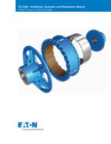
TLC 5004 - Installation, Operation and Maintenance Manual Airflex® Torque Limiting Coupling F;T>N Powering Business Worldwide
Open the catalog to page 1
Torque Limiting Coupling General information Forward this manual to the person responsible for Installation, Operation and Maintenance of the product described herein. Without access to this information, faulty Installation, Operation or Maintenance may result in personal injury or equipment damage. Use Only Genuine Airflex Replacement Parts. The Airflex Division of Eaton Corporation recommends the use of genuine Airflex replacement parts. The use of non-genuine Airflex replacement parts could result in substandard product performance, and may void your Eaton warranty. For optimum performance,...
Open the catalog to page 2
2.3 Mounting spider and drum hub8_ 2.5 Axial locking device adjustment 10 2.6 Installation of single wide element and drum 11 3.2 Control component adjustment 12 4.2 Removal of element assembly and drum 14 4.3 Removal of spider and drum hub 14 4.5 Friction shoe assembly replacement 14 5.0 Spare parts storage 15 6.0 Ordering information/technical assistance 15 7.1 Parts breakdown of TLC element assemblies figures 1 and 10 16 8.1 Parts breakdown of TLC hub, spider, drum, axial locking assy. and rotorseal figure 2 16 9.2 (Standard) Friction shoe assembly, torque bar and release spring kit 17 10.1...
Open the catalog to page 3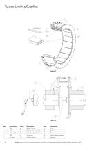
Torque Limiting Coupling Item Description Item Description Item Description 1 Rim 2 Tube 3 Snap rings 4 QRV 5 Air tube 11 Hub 12 Spider 13 Drum 14 Axial locking assembly 15 Rotorseal Rubber washer Friction shoe assembly Side plate (2 required) Torque bar Release spring EATON Torque Limiting Coupling Installation, Operation and Maintenance Manual E-MEQD-II002-E September 2015
Open the catalog to page 4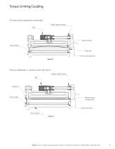
Torque Limiting Coupling Friction shoe assembly retracted Rubber backed washer QRV Release spring Drum surface Torque bar Friction shoe assembly Figure 3 Friction Material in contact with the drum Rubber backed washer QRV Drum surface Release spring (Compressed) Contact with drum Drum surface Figure 4 EATON Torque Limiting Coupling Installation, Operation and Maintenance Manual E-MEQD-II002-E September 2015
Open the catalog to page 5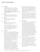
1.0 Introduction Throughout this manual there are a number of HAZARD Warnings that must be read and adhered to in order to prevent possible personal injury and/ or damage to equipment. Three signal words Danger, A Warning and A Caution are used to indicate the severity of a hazard, and are preceded by the safety alert symbol A Danger Denotes the most serious hazard, and is used when serious injury or death WILL result from misuse or failure to follow specific instructions. A Warning Used when serious injury or death MAY result from misuse or failure to follow specific instructions. A Caution...
Open the catalog to page 6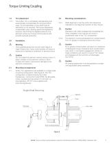
1.3.1 The Airflex TLC is completely self-adjusting and automatically compensates for lining and drum wear. Air line lubrication or any other type of lubrication is not required. The torque developed is dependent upon rotating speed and applied air pressure. By limiting the applied pressure, the element will act as a torque limiting device and provide overload protection. Only qualified personnel should install, adjust or repair these units. Faulty workmanship will result in exposure to hazardous conditions or personal injury. A Caution Do not inflate the element without having a drum in place....
Open the catalog to page 7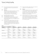
Heat the drum hub or spider uniformly to a maximum of 250°F (121°C) to expand the bores. Caution It is recommended the drum hub or spider be heated in oil or an oven; however, torches may be used. Use several with "rosebud” (broad-flame) tips and keep them moving to avoid "hot spots". Check bore temperature with a temperature reading device frequently to avoid overheating. Slide the heated drum hub or spider onto the shaft. Hold in position and allow them to cool. It is helpful to put a mechanical stop device onto the component face to prevent "over-shooting” the proper axial location if there...
Open the catalog to page 8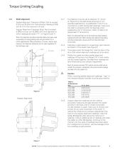
Torque Limiting Coupling Parallel Alignment Tolerance (Offset): Not to exceed 0.010 inch (0.254 mm) Total Indicator Reading (0.005 inch (0.127 mm) maximum off- set). Angular Alignment Tolerance (Gap): Not to exceed 0.0005 inch per inch (0.0005 mm/ mm) diameter at which readings are taken (“D” on Figure 6 and 7). Note: The alignment procedure described below has been used successfully on many grinding mills using an Airflex TLC or clutch application(s). Other procedures, of course, may be used; however, the alignment tolerances are the same regardless of the technique used. Bracket Dial Indicator...
Open the catalog to page 9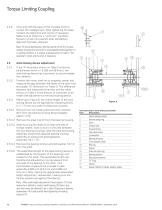
Item description axial locking assembly Item Description 1 Spider adapter plate 2 Internal snap ring 9 Drum adapter plate 12 External snap ring 18 Spacer (Wired to spider adapter plate) Shim and shift the base of the movable shaft to correct the misalignment. After tightening the base, recheck the alignment and correct if necessary. Make sure to check for a "soft foot” condition. Dowel or chock into position after satisfactory aligment has been achieved. Note: On some applications, thermal growth of the mill or gear reducer (if present) may result in unacceptable shaft alignment in a running...
Open the catalog to page 10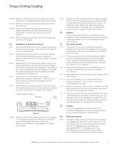
Rotate the motor shaft and push the spider towards the mill until the axial locking device mounting plate is flush against the spider face and the motor is on magnetic center. Attach the axial locking device mounting plate to the spider with the appropriate screws and lock washers. Tighten the screws. Caution Do not attempt to pull the motor shaft back onto magnetic center by tightening the axial locking device mounting screws. To do so will damage the axial locking device. Air control system The typical TLC air control system(s) operating charateristics vary from one grinding mill to another,...
Open the catalog to page 11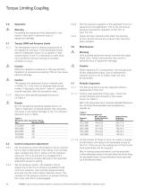
Operation Warning Exceeding the operating limits described in this section may result in personal injury or equipment damage. Torque, RPM and Pressure Limits The developed torque is directly proportional to the applied air pressure. If the developed torque seems inadequate, check for oil, grease or dust contamination of the TLC elements or other drive train conditions that are causing an overload condition to occur. Caution Maximum applied air pressure is 125 psig (8.5 bar). Operation at pressures exceeding 150 psi may cause element damage. Caution The special (non-asbestos) friction material...
Open the catalog to page 12All Eaton Hydraulics catalogs and technical brochures
 KBCG-6-1
16 Pages
 KBCG-3-1*
16 Pages
 LifeSense Master Catalog
58 Pages
 Electronic Feedback Cylinders
48 Pages
 TLC Slip Detect Control Panel
18 Pages
 Success made simple
16 Pages
 Coils
Coils14 Pages
 2 Speed axial piston motor
14 Pages
 Hydraulics Portfolio Brochure
12 Pages
 Eaton HP50
4 Pages
 Eaton Easy Couple H201
2 Pages
 Eaton Delta motor
4 Pages
 Eaton Weatherhead Core
20 Pages
 Eaton Food Processing
26 Pages
 Eaton Aeroquip Core
16 Pages
 Eaton Engineered Solutions
12 Pages
 Eaton EC600 X-FLEX
2 Pages
 Press control blocks
4 Pages
 Eaton Brass Products Master Catalog
166 Pages
 Eaton® Industrial Cylinders
12 Pages
 Airflex® Water-Cooled Brakes
22 Pages
 Airflex® DBB & DBA Brakes
12 Pages
 DG4V-3 70 Design Segment D
10 Pages
 DG3V-8 & DG5V-8 Segment J
30 Pages
 DG3V-7 & DG5V-7 Segment I
16 Pages
 DG3V-3, DG4VP-3 Segment F
10 Pages
 DG5V-7 30 Design & DG3V-7 20
16 Pages
 Eaton Floating Housing Brake
8 Pages
 Track Drive Motor - 2-Speed
16 Pages
 Hydraulic Remote Controls
26 Pages
 CNG Hose Catalog
12 Pages
 External Gear Pump – GD5 Series
24 Pages
 Low Speed, High Torque Motors
294 Pages
 BECODISC Stacked Disc Cartridges
20 Pages
 X20 Series 220 - Pump Catalog
20 Pages
 Eaton Winner LQA Program - EMEA
54 Pages
 Eaton Aeroquip Master Catalog
384 Pages
 Eaton Guardian Seal
4 Pages
 Accumulators Master Catalog
30 Pages
 Filters Master Catalog
156 Pages
 Eaton?s Pump and Motor Products
24 Pages
 E-HOEV-MC001
68 Pages
 E-HOEV
2 Pages
 EH066
EH0662 Pages
 A-HC
A-HC8 Pages


Archived catalogs
 Industrial Hose and Tubing
216 Pages
 509200
4 Pages
 E-HOBV
2 Pages
 A-HOAK
69 Pages
 et3000
19 Pages
 ttc
ttc28 Pages
 ETRLD
ETRLD20 Pages
 x505901
21 Pages
 509400
8 Pages
 v fifi
36 Pages
 i730
i7308 Pages
 E1
E119 Pages
 1E
1E2 Pages
 DP
DP12 Pages
 C001
C00123 Pages
 XQ5
XQ520 Pages
 E2
E221 Pages
 Motion control valves
124 Pages
 GD5-Series
24 Pages
 KBH-05 10 Series
22 Pages
 Fluid Conveyance Master Catalog
196 Pages
 Power amplifier
60 Pages
 EHST-3-40 Series
8 Pages
 Eaton VSQ Vane Pumps
28 Pages
 Eaton STC® Connectors Catalog
48 Pages
 W Series
80 Pages
 DG3V-5 & DG5V-5 Segment H
16 Pages
 DBA
DBA4 Pages
 Accumulators
30 Pages
 GEAR PUMPS AND MOTORS
35 Pages
 ETON MOBILE VALVES
8 Pages
 Hydro-Line® N5 Series Cylinders
36 Pages


- Measuring device
- Liquid filter
- Filter with cartridge
- Filter cartridge
- Industrial use filter
- Pressure separator filter
- Stainless steel pre-filter
- Industrial filter cartridge
- Fine filter cartridge
- Water pre-filter
- Filtration unit
- Filter housing
- Water filter cartridge
- Liquid filter housing
- Plastic filter cartridge
- General purpose filter cartridge
- Hydraulic filter
- Compact pre-filter
- Basket filter
- VOC-free liquid filtration unit