- Catalogs
- Eaton Hydraulics
- DG3V-7 & DG5V-7 Segment I
- Products
- Catalogs
- News & Trends
- Exhibitions
DG3V-7 & DG5V-7 Segment I
1 /16Pages

DG3V-7 & DG5V-7 Segment I
1 /16Pages
Catalog excerpts
Powering Business Worldwide
Open the catalog to page 1
Pilot Operated Directional Valve DG3V-7-30 Design Solenoid Controlled Pilot Operated Directional Valve DG5V-7-50 Design General description DG*V-7 valves are used primarily for controlling the starting, stopping and direction of fluid flow. Two series of valves, DG5V solenoid controlled, pilot operated and DG3V pilot operated models are available with a wide selection of spools. These include meter-in and meterout spools and a regeneration type that can obviate extra valves essential in traditional circuit arrangements. All spools have been designed to provide good low shock, fast response characteristics...
Open the catalog to page 2
Model Code DG3V-7 30 Series, Pilot Operated Directional Valves For pilot operated valves: For solenoid controlled, pilot operated valves: Fluid Compatibility 1 Blank – Standard BUNANitrile Seals F3 – Viton Seals Note: For further information see “Hydraulic Fluids” section on page 13. 2 Spool type See “Functional Symbols” section on pages 5-6. 3 Spool spring arrangement A – Spring offset, end-to-end (P to B when operated) AL – As “A” but left-hand build (P to A when operated) B – Spring offset, endtocenter (P to B when operated) BL – As “B” but left-hand build (P to A when operated) C – Spring...
Open the catalog to page 3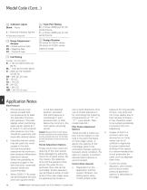
Model Code (Cont...) Indicator Lights 12 Blank – None L – Solenoid indicator lights• • Flying lead coil type only Surge Suppressor/ 13 damper D1 – Diode positive bias D2 – Negative bias D7 – Transorb type 15 Tank Port Rating 6 – 210 bar (3000 psi) for AC performance. 7 – 210 bar (3000 psi) for DC performance. 16 Design Number 20 series for DG3V valves. 30 series for DG5V valves. Subject to change. See Page 7 for circuit details Application Notes Pilot Pressure a. Pilot pressure must always exceed tank line pressure by at least the requisite minimum pilot pressure. This also applies when combining...
Open the catalog to page 4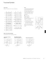
Functional Symbols Spool Types Shown in 3-position form, plus 2 transients. 1. In the detailed and simplified symbols on this and the previous pages, the transient positions are omitted for simplicity. 2. In certain 2-position valves, the “o” position becomes an additional transient, i.e. in DG5V-7-*A(L) and DG5V-7-*N valves. Your Eaton representative can provide further details. Spring Offset, End-to-End, Y2 Opposite Hand, DG3V-7-*AL The following are shown in a DG3V-7-*C example: 1. Pilot choke module 2. Stroke adjusters at either or at both ends (shown at both ends in example) One or more...
Open the catalog to page 5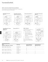
Functional Symbols DG5V-7, Solenoid Controlled, Pilot Operated Models P Comprehensive and simplified symbols shown configured for external pilot supply and internal drain Spring Offset, End-to-End, Spring Offset, End-to-End, Opposite Hand, DG5V-7-*AL DG5V-7-*A Spring Offset, End-to-Center DG5V-7-*B Spring Centered, DG5V-7-*C 3. External pilot connection X SOLENOID IDENTIFICATION Model Spool types (see also in “Model Code” on page 8) DG5V-7-*A/B(-**)(-E)(-T)(-*)-M 1 DG5V-7-*A/B(-**)(-E)(-T)(-*)-VM 2 2 DG5V-7-*AL/BL(-**)(-E)(-T)(-*)-M DG5V-7-*AL/BL(-**)(-E)(-T)(-*)-VM b o a 3 4 X P T Y B DG5V-7-*C/N(-**)(-E)(-T)(-*)-M...
Open the catalog to page 6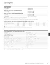
Operating Data MAXIMUM PRESSURES: DG5V-7-**(L)(-*)(-E)(-*) valves, (externally drained); ports: P, A, B, T and X Y DG5V-7-**(L)(-*)(-E)-T(-*) valves, (internally drained)u; ports: P, A, B and X 350 bar (5000 psi) T 210 bar (3045 psi) Pilot pressures See “Pilot Pressures” on page 9 The DG5V, 50 design two-stage valves have been designed to satisfy the needs of most applications. Consult your Eaton representative about an alternative model if: a) Valves are required to remain pressurized for long periods without frequent switching, and /or b) Back pressure on the drain port of externally...
Open the catalog to page 7
Operating Data Pressure drop characteristics See page 9, 10 Response times, DG5V valves: Typical values for a DG5V-7-2C-E spring centered, externally piloted valve under standard test conditions and operating with 150 L/min (40 USgpm) at Coil rating: Pilot pressure, bar (psi): Energizing Time, ms ♦ De-energizing ♦ From applying a signal at the solenoid until the main-stage spool completes its travel A In pure switched circuit conditions, devoid of the effects of any suppression diodes and full-wave rectifiers TEMPERATURE LIMITS:_ Fluid temperature limits See appendix Ambient temperature limits:...
Open the catalog to page 8
Performance Data Pilot Pressures Maximum: 350 bar (5000 psi). Typical minimum differential pilot pressure characteristics, shown below, are based on looped flow through P to A to B to T under standard test conditions. Min. differential pilot pressure Curve correction As drawn Subtract 3 bar (44 psi) As drawn As drawn As drawn Flow rate Pressure drop I FLOW-DIRECTION CURVE REFERENCE SPOOL TYPE P - A B - T Flow rate Pressure Drop Characteristics The following typical pressure drops (p) at flow rates (Q) are based on standard test conditions, using oil of 0,865 specific gravity. Except where otherwise...
Open the catalog to page 9
Installation Dimensions Millimeters (inches) Solenoid Controlled Models with ISO 4400 (DIN 43650) Electrical Connections and Pilot Choke DG5V-7–**(L)(-2)(-E)(-T)(-*)-(V)M–U example For dimensions A, B, C, D and E see page 16 For solenoid identification see page 16 For stroke adjusters see page 15 4 holes, Ø 10,8 (0.42 dia) through, spotfaced Ø 17,0 (0.67 dia). Torque bolts to 49-59 Nm (36-43 lbf ft) 2 holes, Ø 6,5 (0.25 dia) through, spotfaced Ø 11,0 (0.43 dia). Torque bolts to 9-14 Nm (6.6-10.3 lbf ft) AC models: 45 (1.8) DC models: 61 (2.4) For plug options see page A.16. With pilot choke fitted:...
Open the catalog to page 10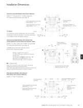
Installation Dimensions Solenoid Controlled Models with Stroke Adjusters DG5V-7-***(L)(-2)(-E)(-T)(-*)-(V)M-U example For solenoid identification see page 16 Pilot choke adjusters, when fitted Stroke adjuster fitted both ends when Model Code 4 = 1 or 3 Stroke adjuster fitted this end when Model Code 4 = 8 or 28 Stroke adjuster fitted this end when Model Code 4 = 7 or 27 Turn locknut counter-clockwise, then turn screw clockwise to shorten stroke, or counter-clockwise to increase stroke. Re-tighten locknut. Solenoid Controlled Models with Junction Box having Optional Terminal Strip and Indicator...
Open the catalog to page 11All Eaton Hydraulics catalogs and technical brochures
 KBCG-6-1
16 Pages
 KBCG-3-1*
16 Pages
 LifeSense Master Catalog
58 Pages
 Electronic Feedback Cylinders
48 Pages
 TLC Slip Detect Control Panel
18 Pages
 Success made simple
16 Pages
 Coils
Coils14 Pages
 2 Speed axial piston motor
14 Pages
 Hydraulics Portfolio Brochure
12 Pages
 Eaton HP50
4 Pages
 Eaton Easy Couple H201
2 Pages
 Eaton Delta motor
4 Pages
 Eaton Weatherhead Core
20 Pages
 Eaton Food Processing
26 Pages
 Eaton Aeroquip Core
16 Pages
 Eaton Engineered Solutions
12 Pages
 Eaton EC600 X-FLEX
2 Pages
 Press control blocks
4 Pages
 Eaton Brass Products Master Catalog
166 Pages
 Eaton® Industrial Cylinders
12 Pages
 Airflex® Water-Cooled Brakes
22 Pages
 Airflex® DBB & DBA Brakes
12 Pages
 DG4V-3 70 Design Segment D
10 Pages
 DG3V-8 & DG5V-8 Segment J
30 Pages
 DG3V-3, DG4VP-3 Segment F
10 Pages
 DG5V-7 30 Design & DG3V-7 20
16 Pages
 Eaton Floating Housing Brake
8 Pages
 Track Drive Motor - 2-Speed
16 Pages
 Hydraulic Remote Controls
26 Pages
 CNG Hose Catalog
12 Pages
 External Gear Pump – GD5 Series
24 Pages
 Low Speed, High Torque Motors
294 Pages
 BECODISC Stacked Disc Cartridges
20 Pages
 X20 Series 220 - Pump Catalog
20 Pages
 Eaton Winner LQA Program - EMEA
54 Pages
 Eaton Aeroquip Master Catalog
384 Pages
 Eaton Guardian Seal
4 Pages
 Accumulators Master Catalog
30 Pages
 Filters Master Catalog
156 Pages
 Industrial Hose and Tubing
216 Pages
 Eaton?s Pump and Motor Products
24 Pages
 E-HOEV-MC001
68 Pages
 E-HOEV
2 Pages
 EH066
EH0662 Pages
 A-HC
A-HC8 Pages
 509200
4 Pages
 E-HOBV
2 Pages
 A-HOAK
69 Pages
 et3000
19 Pages
 ttc
ttc28 Pages
 ETRLD
ETRLD20 Pages
 x505901
21 Pages
 509400
8 Pages
 v fifi
36 Pages
 i730
i7308 Pages
 C001
C00123 Pages
 XQ5
XQ520 Pages
 E2
E221 Pages
 E1
E119 Pages
 1E
1E2 Pages
 DP
DP12 Pages


Archived catalogs
 Motion control valves
124 Pages
 GD5-Series
24 Pages
 KBH-05 10 Series
22 Pages
 Fluid Conveyance Master Catalog
196 Pages
 Power amplifier
60 Pages
 EHST-3-40 Series
8 Pages
 Eaton VSQ Vane Pumps
28 Pages
 Eaton STC® Connectors Catalog
48 Pages
 W Series
80 Pages
 DG3V-5 & DG5V-5 Segment H
16 Pages
 DBA
DBA4 Pages
 Accumulators
30 Pages
 GEAR PUMPS AND MOTORS
35 Pages
 ETON MOBILE VALVES
8 Pages
 Hydro-Line® N5 Series Cylinders
36 Pages


- Liquid filter
- Filter with cartridge
- Filter cartridge
- Industrial use filter
- Pressure separator filter
- Stainless steel pre-filter
- Industrial filter cartridge
- Water pre-filter
- Fine filter cartridge
- Filter housing
- Water filter cartridge
- Liquid filter housing
- Plastic filter cartridge
- General purpose filter cartridge
- Compact pre-filter
- Hydraulic filter
- Basket filter
- Filter element
- Metal filter housing
- In-line filter