- Catalogs
- Eaton Hydraulics
- DG3V-5 & DG5V-5 Segment H
- Products
- Catalogs
- News & Trends
- Exhibitions
DG3V-5 & DG5V-5 Segment H
1 /16Pages

DG3V-5 & DG5V-5 Segment H
1 /16Pages
Catalog excerpts

Powering Business Worldwide
Open the catalog to page 1
Pilot Operated Directional Valve DG3V-5-10 Design Solenoid Controlled Pilot Operated Directional Valve DG5V-5-10 Design General description DG*V-5 valves are used primarily for controlling the starting, stopping and direction of fluid flow. Two series of valves, DG5V solenoid controlled, pilot operated and DG3V pilot operated models are available with a wide selection of spools. These include meterin and meter-out spools and a regeneration type that can obviate extra valves essential in traditional circuit arrangements. Features and Benefits All spools have been designed to provide good low shock,...
Open the catalog to page 2
Model Codes For pilot operated valves: For solenoid controlled, pilot operated valves: F6 – Viton 1 Blank – Buna Nitrile/ High CAN 2 Spool Type See “Functional Symbols” section on pages 5-6. Spool Spring 3 Arrangement A – Spring offset, end-to-end AL – Same as “A” but left hand build B – Spring offset, end-tocenter BL – Same as “B” but left hand build C – Spring centered N – No-spring detented 4 Spool Control 1 – Stroke adjustments, both ends 2 – Pilot choke (dual) adjustments 27 – Dual pilot choke and stroke adjustment “A” port end only 28 – Dual pilot choke and stroke adjustment...
Open the catalog to page 3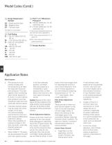
Model Codes (Contd.) damper D1 – Diode positive bias D2 – Negative bias D7 – Transorb type See Page12 for circuit details 14 Coil Rating B – 110V AC 50Hz/120V AC 60 Hz BL – 110V 50 Hz/120V 60 Hz D – 220V AC 50 Hz/240V AC 60 Hz DS – 28V DC 30 watt G – 12V DC GL – 12V DC H – 24V DC HL – 24V DC HM – 24V DC 8 watt 15 Port T or Y Maximum Pressure† 6 – 160 bar (2300 psi), for AC solenoids only 7 – 210 bar (3000 psi), for DC solenoids only † This pressure rating (determined by the pilot valve drain port) is applicable to: 1. Port T when using internal drain (“T” at position 6) 2. Port Y when using external...
Open the catalog to page 4
Functional Symbols Spool Types Shown in 3-position form, plus 2 transients. In certain 2-position valves, the “o” position becomes an additional transient, i.e. in DG5V-5-**A(L) and DG5V-5-**N valves. 52 DG3V-5 Pilot Operated Models Comprehensive and simplified symbols. DG3V-5-**C Models with Pilot Choke Module Obtained by specifying “2” at Model Code position 4 Spring Centered, DG3V-5-**C Spool types: All Note that for clarity pilot lines (dotted lines in illustrations) are omitted from the main-stage nameplate. “a” and “b” interchanged for spool type 8 Typical illustrations for: Control elements...
Open the catalog to page 5
Spring Offset, End-to-End, Opposite Spring Offset, End-to-Center, Hand, DG5V-5-**AL Opposite Hand Models Spool types: 0, 2, 6,Spool types 52 DG5V-5-*B 8 DG5V-5-**BL 0, 2, 52 Spring Offset, End-to-Center Models Spool types DG5V-5-**B 0, 2, 52 DG5V-5-*BL 8 Spring Centered, DG5V-5-**C DG5V-5 Options Detented, DG5V-5-**N Spring Offset, End-to-Center, Opposite Spool types: All Spring Offset, End-to-End, Spool types: 0, 2, 6, 52 Opposite Hand Hand, DG5V-5-**AL The following are shown Models Spool types Spool types: 0, 2, 6, 52 DG5V-5-**C example: DG5V-5-*B 8 DG5V-5-**BL 0, 2, 52 Spring Centered, DG5V-5-**C...
Open the catalog to page 6
Operating Data MAXIMUM PRESSURES: DG5V-5-**(L)(-*)(-E)(-*) valves, (externally drained); ports: P, A, B, T and X Y with AC solenoid Y with DC solenoid DG5V-5-**(L)(-*)(-E)-T(-*) valves, (internally drained)u; ports: P, A, B and X T with AC solenoid T with DC solenoid Maximum flow (for both DG3V-5 and DG5-V5) Pilot pressures The DG5V, 50 design two-stage valves have been designed to satisfy the needs of most applications. 350 bar (5000 psi) 160 bar (2300 psi) 210 bar (3000 psi) 160 L/min (42Usgpm) refer segment B for pilot valve data Consult your Eaton representative about an alternative model...
Open the catalog to page 7
Operating Data TEMPERATURE LIMITS: Fluid temperature limits See appendix Ambient temperature limits: See appendix Minimum ambient, all valves -20°C (-4°F] Maximum ambients, DG5V valves with coils listed in 12 in "Model Code" two pages back, and under conditions stated below: Dual-frequency coils DC coils at 110% of rated voltage 70°C (158°F) INSTALLATION DIMENSIONS: Mass (weight), basic models: kg (lb) approx. ♦ Add 1,1 kg (2.4 lb) when pilot chock adjustment is fitted. Note : For information on pilot valves please refer segment B of the catalog
Open the catalog to page 8
Performance Data Pilot Pressures Differential pressure, i.e. pilot pressure at port P (or port X) minus pilot drain pressure at port T (or port Y). All main stages are spring centered. Selection of spool offset positions “a” or “b” requires pilot pressure equal to or in excess of the above minimums to move the spool against the spring force. This is particularly important when using external pilot pressure supply. Maximum 315 bar (4567 psi) Minimum (for max. flow): For spool types 0, 1, 8 , 11 4,5 bar (65 psi) For spool type 6 8 bar (116 psi) When using a type 8 spool with the valve configured...
Open the catalog to page 9
Installation Dimensions Millimeters (inches) Solenoid Controlled Models with ISO 4400 (DIN 43650) Electrical Connections and Optional Pilot Choke DG5V-5-**(L)(-2)(-E)(-T)(-*)-(V)M-U example For solenoid identification see previous page. Main port P Main port A Main port T B (Usable with Eaton SystemStak valves and some subplates, see catalog 2022 and 2425 respectively) Mounting bolt centers For coil removal: AC models: 45 (1.8) DC models: 61 (2.4) 4 holes for mounting bolts, Ø7,02 (0.27 dia) through, spotfaced Ø11,0 (0.43 dia). Recommended bolt torques: Up to 210 bar (3000 psi): 12–14 Nm (9-10...
Open the catalog to page 10
Installation Dimensions Solenoid Controlled Models with Junction Box having Optional Terminal Strip and Indicator Lights For solenoid identification see page A.7. Available also with other options shown on previous and following pages. Ground connection Ø4,0 (0.16 dia) self-tapping screw M20-6H x 1,5 thread for F(T)J options, or NPT for F(T)W options, at both ends. Closure plug fitted at one end. For other options see 10 & 11 in “Model Code” on page A.5 and under “NFPA Connector--- ” and “Terminal Strip and Lights”, on pages A.10 and A.11. Ref. “Model Code” : Codes “FJ” and “FW” 10 Codes “FTJ”...
Open the catalog to page 11All Eaton Hydraulics catalogs and technical brochures
 KBCG-6-1
16 Pages
 KBCG-3-1*
16 Pages
 LifeSense Master Catalog
58 Pages
 Electronic Feedback Cylinders
48 Pages
 TLC Slip Detect Control Panel
18 Pages
 Success made simple
16 Pages
 Coils
Coils14 Pages
 2 Speed axial piston motor
14 Pages
 Hydraulics Portfolio Brochure
12 Pages
 Eaton HP50
4 Pages
 Eaton Easy Couple H201
2 Pages
 Eaton Delta motor
4 Pages
 Eaton Weatherhead Core
20 Pages
 Eaton Food Processing
26 Pages
 Eaton Aeroquip Core
16 Pages
 Eaton Engineered Solutions
12 Pages
 Eaton EC600 X-FLEX
2 Pages
 Press control blocks
4 Pages
 Eaton Brass Products Master Catalog
166 Pages
 Eaton® Industrial Cylinders
12 Pages
 Airflex® Water-Cooled Brakes
22 Pages
 Airflex® DBB & DBA Brakes
12 Pages
 DG4V-3 70 Design Segment D
10 Pages
 DG3V-8 & DG5V-8 Segment J
30 Pages
 DG3V-7 & DG5V-7 Segment I
16 Pages
 DG3V-3, DG4VP-3 Segment F
10 Pages
 DG5V-7 30 Design & DG3V-7 20
16 Pages
 Eaton Floating Housing Brake
8 Pages
 Track Drive Motor - 2-Speed
16 Pages
 Hydraulic Remote Controls
26 Pages
 CNG Hose Catalog
12 Pages
 External Gear Pump – GD5 Series
24 Pages
 Low Speed, High Torque Motors
294 Pages
 BECODISC Stacked Disc Cartridges
20 Pages
 X20 Series 220 - Pump Catalog
20 Pages
 Eaton Winner LQA Program - EMEA
54 Pages
 Eaton Aeroquip Master Catalog
384 Pages
 Eaton Guardian Seal
4 Pages
 Accumulators Master Catalog
30 Pages
 Filters Master Catalog
156 Pages
 Industrial Hose and Tubing
216 Pages
 Eaton?s Pump and Motor Products
24 Pages
 E-HOEV-MC001
68 Pages
 E-HOEV
2 Pages
 EH066
EH0662 Pages
 A-HC
A-HC8 Pages
 509200
4 Pages
 E-HOBV
2 Pages
 A-HOAK
69 Pages
 et3000
19 Pages
 ttc
ttc28 Pages
 ETRLD
ETRLD20 Pages
 x505901
21 Pages
 509400
8 Pages
 v fifi
36 Pages
 i730
i7308 Pages
 C001
C00123 Pages
 XQ5
XQ520 Pages
 E2
E221 Pages
 E1
E119 Pages
 1E
1E2 Pages
 DP
DP12 Pages


Archived catalogs
 Motion control valves
124 Pages
 GD5-Series
24 Pages
 KBH-05 10 Series
22 Pages
 Fluid Conveyance Master Catalog
196 Pages
 Power amplifier
60 Pages
 EHST-3-40 Series
8 Pages
 Eaton VSQ Vane Pumps
28 Pages
 Eaton STC® Connectors Catalog
48 Pages
 W Series
80 Pages
 DBA
DBA4 Pages
 Accumulators
30 Pages
 GEAR PUMPS AND MOTORS
35 Pages
 ETON MOBILE VALVES
8 Pages
 Hydro-Line® N5 Series Cylinders
36 Pages


- Liquid filter
- Filter with cartridge
- Filter cartridge
- Industrial use filter
- Pressure separator filter
- Stainless steel pre-filter
- Industrial filter cartridge
- Water pre-filter
- Fine filter cartridge
- Filter housing
- Water filter cartridge
- Liquid filter housing
- Plastic filter cartridge
- General purpose filter cartridge
- Compact pre-filter
- Hydraulic filter
- Basket filter
- Filter element
- Metal filter housing
- In-line filter