- Products
- Catalogs
- News & Trends
- Exhibitions
Coils
1 /14Pages

Coils
1 /14Pages
Catalog excerpts
X70 Plugin motor catalog Powering Business Worldwide
Open the catalog to page 1
X70 PLUGIN MOTOR CATALOG
Open the catalog to page 2
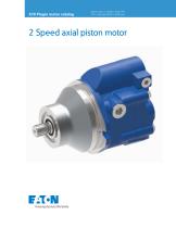
2 Speed axial piston motor Eaton Medium Duty Piston Motors convert hydraulic energy supplied by the pump to mechanical energy. These motors are uniquely suited to fit any application that requires continuous rotary motion at a remote location from the power source. Axial piston motors share the design advantages of piston pumps to provide long-lasting power in a lightweight, easily serviceable package. The table below provides an overview of features. For a complete list of options, refer to the Model Code section of a given motor displacement. Field proven rotating group design 2 speed option...
Open the catalog to page 3
Technical specifications Parameter Maximum rated speed at rpm maximum displacement Maximum rated speed at rpm minimum displacement Nominal pressure rating * bar [psi] Peak pressure rating ** bar [psi] Output torque (theoretical) N-m / bar [lbf-in/1000 psi] Shift pressure range bar [psi] Maximum allowable case pressure bar [psi] Viscosity - Minimum cSt Viscosity - Optimum working range cSt Viscosity - Maximum cSt Maximum Fluid Temp-Inlet °C Minimum Fluid Operating Temp °C Ambient Temperature °C Weight lbs [kg] Notes: * Nominal pressure : Max. delta...
Open the catalog to page 4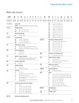
X7M X70 variable displacement piston motor Mounting flange A Plug-in mount Output shaft 01 15 Tooth 16/32 Spline Main ports sizing A M27 X 2 Metric O-Ring port (A & B) B 1.0625-12 UN-2B SAE o-ring port (A & B) Port orientation 1 Radial ports Motor control options A Single input directly operated, external control supply, without pilot valve Control solenoids 0 None Supply orifice 0 No orifice 1 Shuttle valve with loop flushing 2 Blocked shuttle valves 3 Anti cavitation valve, unidirectional LH (CCW) Rotation 4 Anti cavitation valve, unidirectional RH Flushing...
Open the catalog to page 5
2 Speed axial piston motor Loop flushing valve The spring centered shuttle valve, located in the motor’s end cover, moves to connect the low pressure side of the loop to the low pressure relief valve. When back pressure gets high enough the low pressure relief valve, in the end cover, opens and charge pump flow enters the motor case. Case flow flushes the pump and motor cases and helps keep the transmission cool. The low pressure relief valve in the motor’s end cover typically has a lower setting than the charge pressure relief valve in the charge pump. This is so case flow will begin at the...
Open the catalog to page 6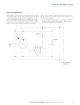
2 Speed axial piston motor Anti cavitation valve 1 allow flow from delivery side back to suction side of motor. So, ultimately motor suction will get the required flow to run motor at desired speed. Anti-cavitation valve is to prevent the cavitation of the motor during deceleration and spin down. These are the conditions in which pump does not generate sufficient flow to fulfill motor requirements. Reduced flow creates vacuum at the motor suction which intern reduces pressure below partial pressure and arises cavitation. By introduction of the check valve in the circuit this condition will get...
Open the catalog to page 7
2 Speed axial piston motor Brake release port X70 series plugin motors are provided with a brake release port to allow the user to make an access to the brake-release feature of the machine gear box from the rear side of the motor. While all motors will have the brake release port, not all gearboxes are compatible with this motor feature. Get in touch with your EATON representative in case of queries. The rated pressure for the brake release port on the motor housing is 250 bar (this does take into account the O-ring interface between the motor and gearbox). Check your gearbox for compatibility...
Open the catalog to page 8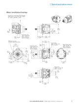
2 Speed axial piston motor Motor installation drawings Requires an o-ring: Viton 75 Durometer cross section -2.6 ± 0.07[0.103 ± 0.003] I.D. -126.6 ± 0.8[4.987 ± 0.035] Case drain side .750 - 16 UNF -2B SAE o-ring port (shown plugged) Mating o-ring min installed inside Ø4.8 [0.19] Case drain side .750 -16 UNF - 2B SAE o-ring port (shown plugged) 102.4 [4.03] Control port .5625 - 18 UNF - 2B SAE o-ring port Brake release port .4375 - 20 UNF - 2B SAE o-ring port (shown plugged) 1 Main ports 1.0625 - 12 UN - 2B SAE o-ring port X70 PLUGIN MOTOR CATALOG
Open the catalog to page 9
2 Speed axial piston motor Shaft installation drawings 15 Tooth 30º flat root side fit 16/32 class 5 spline per ANSI B92.1 Hydraulic System Design Calculations Basic Formulas Component selection The following components are necessary for transmission operation: The long service life of Eaton hydrostatic transmissions is largely dependent on the proper selection and installation of the components necessary for transmission operation. Variable displacement pump Fixed or variable displacement motor Reservoir Filter Charge pump inlet line Pump and motor case drain lines High pressure lines Heat exchanger...
Open the catalog to page 10
Reservoir The reservoir is an important part of the hydrostatic transmission system. It should provide adequate oil storage and allow easy oil maintenance. The reservoir must hold enough oil to provide a continuous oil supply to the charge pump inlet. It must also have enough room for the hydraulic oil to expand as the system warms up. Consider charge pump flow when sizing the reservoir: One half (.5) minute times (X) the maximum charge pump flow should be the minimum oil volume in the reservoir. Maintaining this oil volume will give the oil a minimum of thirty (30) seconds in the reservoir....
Open the catalog to page 11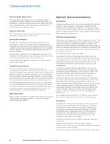
Heat exchanger bypass valve The heat exchanger bypass valve is a pressure and/or temperature valve in parallel with the heat exchanger. Its purpose is to prevent case pressures from getting too high. The heat exchanger bypass valve opens when the oil is thick, especially during cold starts. Reservoir return line The same general requirements that apply to case drain lines apply to the reservoir return line. Bearing life estimation Bearing life is defined as the length of time in terms of revolutions or time until a fatigue failure. Bearing load is calculated as a reaction which is derived from...
Open the catalog to page 12All Eaton Hydraulics catalogs and technical brochures
 KBCG-6-1
16 Pages
 KBCG-3-1*
16 Pages
 LifeSense Master Catalog
58 Pages
 Electronic Feedback Cylinders
48 Pages
 TLC Slip Detect Control Panel
18 Pages
 Success made simple
16 Pages
 2 Speed axial piston motor
14 Pages
 Hydraulics Portfolio Brochure
12 Pages
 Eaton HP50
4 Pages
 Eaton Easy Couple H201
2 Pages
 Eaton Delta motor
4 Pages
 Eaton Weatherhead Core
20 Pages
 Eaton Food Processing
26 Pages
 Eaton Aeroquip Core
16 Pages
 Eaton Engineered Solutions
12 Pages
 Eaton EC600 X-FLEX
2 Pages
 Press control blocks
4 Pages
 Eaton Brass Products Master Catalog
166 Pages
 Eaton® Industrial Cylinders
12 Pages
 Airflex® Water-Cooled Brakes
22 Pages
 Airflex® DBB & DBA Brakes
12 Pages
 DG4V-3 70 Design Segment D
10 Pages
 DG3V-8 & DG5V-8 Segment J
30 Pages
 DG3V-7 & DG5V-7 Segment I
16 Pages
 DG3V-3, DG4VP-3 Segment F
10 Pages
 DG5V-7 30 Design & DG3V-7 20
16 Pages
 Eaton Floating Housing Brake
8 Pages
 Track Drive Motor - 2-Speed
16 Pages
 Hydraulic Remote Controls
26 Pages
 CNG Hose Catalog
12 Pages
 External Gear Pump – GD5 Series
24 Pages
 Low Speed, High Torque Motors
294 Pages
 BECODISC Stacked Disc Cartridges
20 Pages
 X20 Series 220 - Pump Catalog
20 Pages
 Eaton Winner LQA Program - EMEA
54 Pages
 Eaton Aeroquip Master Catalog
384 Pages
 Eaton Guardian Seal
4 Pages
 Accumulators Master Catalog
30 Pages
 Filters Master Catalog
156 Pages
 Industrial Hose and Tubing
216 Pages
 Eaton?s Pump and Motor Products
24 Pages
 E-HOEV-MC001
68 Pages
 E-HOEV
2 Pages
 EH066
EH0662 Pages
 A-HC
A-HC8 Pages
 509200
4 Pages
 E-HOBV
2 Pages
 A-HOAK
69 Pages
 et3000
19 Pages
 ttc
ttc28 Pages
 ETRLD
ETRLD20 Pages
 x505901
21 Pages
 509400
8 Pages
 v fifi
36 Pages
 i730
i7308 Pages
 C001
C00123 Pages
 XQ5
XQ520 Pages
 E2
E221 Pages
 E1
E119 Pages
 1E
1E2 Pages
 DP
DP12 Pages


Archived catalogs
 Motion control valves
124 Pages
 GD5-Series
24 Pages
 KBH-05 10 Series
22 Pages
 Fluid Conveyance Master Catalog
196 Pages
 Power amplifier
60 Pages
 EHST-3-40 Series
8 Pages
 Eaton VSQ Vane Pumps
28 Pages
 Eaton STC® Connectors Catalog
48 Pages
 W Series
80 Pages
 DG3V-5 & DG5V-5 Segment H
16 Pages
 DBA
DBA4 Pages
 Accumulators
30 Pages
 GEAR PUMPS AND MOTORS
35 Pages
 ETON MOBILE VALVES
8 Pages
 Hydro-Line® N5 Series Cylinders
36 Pages


- Liquid filter
- Filter with cartridge
- Filter cartridge
- Industrial use filter
- Pressure separator filter
- Stainless steel pre-filter
- Industrial filter cartridge
- Water pre-filter
- Fine filter cartridge
- Filter housing
- Water filter cartridge
- Liquid filter housing
- Plastic filter cartridge
- General purpose filter cartridge
- Compact pre-filter
- Hydraulic filter
- Basket filter
- Filter element
- Metal filter housing
- In-line filter