- Catalogs
- Eaton Commercial Controls
- Eaton E32 3-switch modules
Eaton E32 3-switch modules
1 /12Pages

Eaton E32 3-switch modules
1 /12Pages
Catalog excerpts

Effective October 2012 Supersedes March 2011 Eaton E32 3-switch modules Description Contents Description 1 System description . . . . . . . . . . . . . . . . . . . . 2 2 Rocker switch modules . . . . . . . . . . . . . . . . . 2 2.1 Lighting . . . . . . . . . . . . . . . . . . . . . . . . 2 2.2 Rocker circuits . . . . . . . . . . . . . . . . . . . 2 2.3 Dimensions and cutout . . . . . . . . . . . . 3 2.4 Connections: Master . . . . . . . . . . . . . . 3 2.5 Connections: Expansion . . . . . . . . . . . 3 2.6 Connector . . . . . . . . . . . . . . . . . . . . . . 4 3 Modes of operation . . . . . . . . . . . . . . . . . . . . 4 3.1 Normal mode . . . . . . . . . . . . . . . . . . . . 4 3.2 Sleep mode . . . . . . . . . . . . . . . . . . . . . 4 3.3 Wake on CAN message. . . . . . . . . . . . 4 3.4 Wake on switch press . . . . . . . . . . . . . 4 4 Switch reporting . . . . . . . . . . . . . . . . . . . . . . 4 5 Module address . . . . . . . . . . . . . . . . . . . . . . . 4 5.1 Master address . . . . . . . . . . . . . . . . . . 4 5.2 Master addressing . . . . . . . . . . . . . . . . 4 5.3 Expansion module address . . . . . . . . . 4 5.4 Expansion switch press addressing . . . . . . . . . . . . . . . . . . . . 4 5.5 Address assignment faults . . . . . . . . . 5 5.6 Expansion address by CAN message . . . . . . . . . . . . . . . . . 5 5.7 Indicator module address assignment. . . . . . . . . . . . . . . . . . . . 5 5.8 Master service swap . . . . . . . . . . . . . . 5 5.9 Expansion service swap . . . . . . . . . . . 5 6 Master module digital output . . . . . . . . . . . 5 7 Watchdog . . . . . . . . . . . . . . . . . . . . . . . . . . . . 6 8 CAN controller diagnostics. . . . . . . . . . . . . . 6 9 Part number and revision information . . . . 6 10 System faults . . . . . . . . . . . . . . . . . . . . . . . . . 6 11 Message structure . . . . . . . . . . . . . . . . . . . . . 6 11.1 Messages sent to Eaton master . . . . . 6 11.2 Messages sent by Eaton master . . . . . 6 11.3 CAN 2.0b 29 bit header . . . . . . . . . . . . 7 11.4 Data portion of message . . . . . . . . . . . 7 12 EATON CAN messages . . . . . . . . . . . . . . . . . 8 12.1 Diagnostic fault messages . . . . . . . . . 8 12.2 System message . . . . . . . . . . . . . . . . . 8 12.3 Status message . . . . . . . . . . . . . . . . . . 9 12.4 Module types on master . . . . . . . . . . . 9 12.5 Switch press messages . . . . . . . . . . . . 9 12.6 Wake system on switch press . . . . . . 9 12.7 Indicator lighting . . . . . . . . . . . . . . . . 10 12.8 Icon LED control . . . . . . . . . . . . . . . . 10 12.9 Indicator and icon brightness level . . 11 12.10 Digital output control . . . . . . . . . . . . . 11 12.11 Special function messages . . . . . . . . 11 13 Environmental and electronic specifications . . . . . . . . . . . . . . . . . . . . . . 11 14 Troubleshooting . . . . . . . . . . . . . . . . . . . . . . 12
Open the catalog to page 1
System description The Eaton eSM hardware system is designed with a master module that connects to other ECUs via SAE J1939 CAN 2.0b. The master communicates with Eaton expansion modules using LIN 2.0. Each master can support up to seven expansion modules. Features Center indicator has up to four colors for status information Long life switches: 500,000+ cycles Easy address assignment All lighting is controlled by CANbus message. Off On Slow flash 1 Hz Fast flash 2 Hz Short flash 200 ms On/800 ms Off Long flash 800 ms On/200 ms Off Wake/Sleep flash 250 ms On/4000 ms Off Immune to SAE J1455 and...
Open the catalog to page 2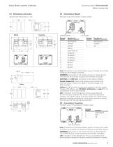
Technical Data TD07002002E Effective October 2012 Connections: Master The back cover of the master module is black. Expansion Terminal Number Function for Master Connector Terminal Number Function for Expansion Connector Vbat: Connection to the vehicle battery power. The Vbat pins of each connector are internally connected. COMMON: Connection to the vehicle common or chassis ground. The common pins of each connector are internally connected. CAN High and CAN Low: Connection to the vehicle CANbus. System Awake Out: Output that sources current (active high) when the system wakes from sleep on a...
Open the catalog to page 3
Tyco Part Number Housing, 3-pin Housing, 12-pin Cover, 12-pin Terminal 20 AWG Terminal 22 AWG Terminal 24–28 AWG Connector Eaton Part Number 1-1718346-1 1394048-1 2-1355524-3 5-963715-1 (Strip form) 963729-1 (Loose piece) 5-928999-1-1 (Strip) 963726-1 (Loose piece) 1355717-1 (Strip) 1355718-1 (Loose piece) Normal mode In normal mode all operational features of the product are active. Sleep mode The system has a power saving sleep mode. The modules are put into sleep mode by CAN message. Sleep mode reduces current draw on the battery. During sleep mode: Module address Each module has an address...
Open the catalog to page 4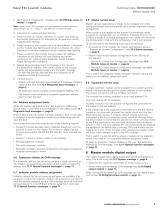
Technical Data TD07002002E Effective October 2012 3. Send second configuration message (see 12.4 Module types on master on page 9). Note: Above three CAN messages must be received in order and with a delay between 20 ms < delay < 1 sec (500 ms is recommended). 4. Indicators on master will start flashing. 5. Press a switch on master, indicators on master stop flashing and remain continuous On. Indicators on all expansion switch modules start flashing. 6. Press a switch on the module that is to have address 1. Indicators on this module stop flashing and remain continuous On, while Indicators on...
Open the catalog to page 5
The master and expansion modules implement a hardware watchdog. Source Address Message Length If the code stops executing properly the system will reset and report the fault using diagnostic fault message (see 12.1 Diagnostic fault messages on page 8). The master module has a basic CAN diagnostics feature. The master module stores the counts of the CAN controller state changes. The master module sends the counts when it receives a request (see 12.2 System message on page 8). Part number and revision information Each device contains manufacturing, part number and revision information. This information...
Open the catalog to page 6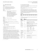
Technical Data TD07002002E Effective October 2012 Byte 0 bit 0 = Data page: This is not used, set to 0 bit 1 = Extended data page: Not used, set to 0 bits 2…3 = Low order bits of the three bit priority bit 4 = High order bit of the three bit priority bits 5…7 = Not used, set to 0 Byte 1 PDU format = (EFh) for proprietary messages sent to a specific device (FFh) for proprietary message sent as broadcast to all devices on network DFh—STOP BROADCAST (DM 13) D9h—Memory Access Request (DM 14) D8h—Memory Access Response DM(15) D7h—Binary Data Transfer (DM 16) D6h—Boot Load Data (DM 17) D4h—Data Security...
Open the catalog to page 7All Eaton Commercial Controls catalogs and technical brochures
 Toggle Switches
35 Pages
 Toggle switch accessories
4 Pages
 Rockers
104 Pages
 Low voltage busway
49 Pages
 Electronic Products
17 Pages
 Eaton E31 keypad modules
12 Pages
 Dimmers and Wipers
6 Pages
 Special Devices
10 Pages
 Pushbuttons
23 Pages


Archived catalogs
 eMobility
25 Pages
 eMobility
56 Pages
 Buildings solutions
8 Pages
 Toggle Switches
29 Pages
 Pushbutton Switches
13 Pages
 Switches - 3100-3200 Series
4 Pages
 Switches - 1600-2600 Series
6 Pages
 Switches - 1500-2500 Series
4 Pages


- Single-pole switch
- Push-button switch
- Technology switch
- Multipole switch
- Electromechanical switch
- Safety electric switch
- Rotary electric switch
- IP67 switch
- Plastic switch
- Bipolar switch
- Hermetic switch
- Technology push-button switch
- Electromechanical push-button switch
- Illuminated switch
- AC electric switch
- Lever switch
- On/off switch
- DC switch
- Heavy-duty switch