
- Catalogs
- Eaton Commercial Controls
- Eaton E31 keypad modules


Eaton E31 keypad modules

Eaton E31 keypad modules
The Eaton eSM hardware system includes a master module that interfaces with other ECUs via SAE J1939 CAN 2.0b and communicates with Eaton expansion modules using LIN 2.0. Each master can support up to seven expansion modules. Key features include four lighted indicators per switch, durable switches, straightforward address assignment, and resilience to power disturbances.
Keypad modules feature icons and four indicators per switch, with non-latching momentary switches. They are sealed to IP66, IP67, and IP68 standards. Lighting is managed by CANbus messages, offering various flash modes. Icons are laser-etched and can be controlled individually or collectively.
The master module connects to the vehicle battery, common ground, CANbus, and LIN data bus. Expansion modules have similar connections and can be daisy-chained using standard sealed Deutsch DT Series connectors.
Normal mode activates all features, while sleep mode reduces power consumption. The system can wake from sleep via CAN message or switch press, with designated functions to wake the system.
The master module broadcasts switch statuses on the CANbus, sending immediate messages upon switch press and regular updates otherwise.
Modules have unique addresses for identification. Master addresses are stored in non-volatile memory and can be set via CAN message or switch press. Expansion modules have addresses between 1 and 7, assigned through a specific process.
Faults during address assignment trigger indicator flashes and require a correct cycle to clear. Common faults include timeouts, missing modules, and configuration mismatches.
Masters and expansion modules can be swapped into configured systems, with automatic address assignment for seamless integration.
The document outlines the process for assigning addresses to modules in a system. When a factory default module is connected, the master module assigns addresses based on the presence of valid addresses and factory defaults. Only one module can be replaced at a time to avoid address conflicts.
A watchdog mechanism ensures system reliability in electromagnetically influenced environments. It resets the system to a defined state if the application is not running reliably, reporting faults via diagnostic messages.
The master module includes basic diagnostics for the CAN controller, storing state change counts and sending them upon request.
Devices contain manufacturing details, part numbers, and revision information accessible via CAN message requests. This data is stored in ASCII format and includes hardware and software part numbers, version numbers, manufacturing dates, and serial numbers.
Faults in the system are reported on the CANbus, with specific diagnostic fault messages detailing the nature of the faults.
Eaton messages follow the J1939 CAN message specification with a 29-bit header and 8 bytes of data. The header identifies the source and destination, and the data portion includes a descriptor and message data.
These messages indicate which device is sending a fault, detailing the device number, type, and fault type.
Used for various system functions such as entering sleep mode, requesting configuration, and resetting watchdog counters.
These messages confirm address assignment completion and request system configuration from electronic control modules.
Messages identify the types of expansion modules attached to the master, necessary for expansion switch press addressing.
When a switch is pressed, the master sends a message on the CANbus, using binary values to report switch status.
This document provides technical specifications and operational guidelines for Eaton E31 keypad modules, focusing on CAN communication, indicator control, and environmental specifications.
- Expansion modules are numbered from 3 to 7, with corresponding switch numbers from 1 to 8.
- Switches can be programmed to wake the system from sleep mode.
- Indicators can be set to various states (OFF, ON, flashing) and are reset to OFF in sleep mode.
- Specific bit values control the flash rates and durations.
- Icon LEDs have similar control options as indicators, with specific bit values for flash formats.
- Icons are OFF in sleep mode but can be controlled as a group using system messages.
- Brightness levels for indicators and icons can be set and retained even when the device is turned off.
- Used to set expansion module addresses via CAN messages.
- Operational temperature range: -40°C to +85°C.
- Storage temperature range: -40°C to +95°C.
- Operational voltage: 9 to 32 Vdc.
- Degree of protection: IP68.
- Mechanical shock and vibration specifications are provided.
- Common issues include CAN message errors, address setting problems, and indicator malfunctions.
- Solutions involve checking CAN configurations, ensuring correct module addresses, and verifying system messages.
Catalog excerpts

Effective October 2012 Supersedes March 2011 Eaton E31 keypad modules Contents Description 1 System description . . . . . . . . . . . . . . . . . . . . 2 2 Keypad modules . . . . . . . . . . . . . . . . . . . . . . 2 2.1 Lighting. . . . . . . . . . . . . . . . . . . . . . . . . . 2 2.2 Icons . . . . . . . . . . . . . . . . . . . . . . . . . . . 2 2.3 Status bar/indicators . . . . . . . . . . . . . . . . 2 2.4 Dimensions and cutout . . . . . . . . . . . . . 3 2.5 Connections: Master . . . . . . . . . . . . . . . 3 2.6 Connections: Expansion . . . . . . . . . . . . 3 2.7 Connector . . . . . . . . . . . . . . . . . . . . . . . 3 3 Modes of operation . . . . . . . . . . . . . . . . . . . 3 3.1 Normal mode . . . . . . . . . . . . . . . . . . . . . 3 3.2 Sleep mode . . . . . . . . . . . . . . . . . . . . . . 3 3.3 Wake on CAN message . . . . . . . . . . . . 3 3.4 Wake on switch press . . . . . . . . . . . . . . 3 4 Switch reporting . . . . . . . . . . . . . . . . . . . . . . 3 5 Module address . . . . . . . . . . . . . . . . . . . . . . 3 5.1 Master address . . . . . . . . . . . . . . . . . . . 4 5.2 Master addressing . . . . . . . . . . . . . . . . . 4 5.3 Expansion module address . . . . . . . . . . 4 5.4 Expansion switch press addressing . . . 4 5.5 Address assignment faults . . . . . . . . . . 4 5.6 Expansion address by CAN message. . . . . . . . . . . . . . . . . . . 4 5.7 Master service swap . . . . . . . . . . . . . . . 4 5.8 Expansion service swap . . . . . . . . . . . . 5 6 Watchdog . . . . . . . . . . . . . . . . . . . . . . . . . . . . 5 7 CAN controller diagnostics. . . . . . . . . . . . . . 5 8 Part number and revision information . . . . 5 9 System faults . . . . . . . . . . . . . . . . . . . . . . . . 5 10 Message structure . . . . . . . . . . . . . . . . . . . . . 5 10.1 Messages sent to Eaton master . . . . . . 5 10.2 Messages sent by Eaton master . . . . . . 6 10.3 CAN 2.0b 29 bit header . . . . . . . . . . . . . 6 10.4 Data portion of message . . . . . . . . . . . . 6 11 Eaton CAN messages . . . . . . . . . . . . . . . . . . 7 11.1 Diagnostic fault messages . . . . . . . . . . 7 11.2 System message . . . . . . . . . . . . . . . . . . 7 11.3 Status message . . . . . . . . . . . . . . . . . . . 8 11.4 Module types on master . . . . . . . . . . . . 9 11.5 Switch press messages . . . . . . . . . . . . . 9 11.6 Wake system on switch press . . . . . . 10 11.7 Indicator lighting . . . . . . . . . . . . . . . . . 10 11.8 Indicator 2 bit commands . . . . . . . . . . 11 11.9 Icon LEDs control . . . . . . . . . . . . . . . . 11 11.10 Indicator and icon brightness level . . . 11 11.11 Special function messages . . . . . . . . . 12 12 Environmental and electronic specifications . . . . . . . . . . . . . 12 13 Troubleshooting . . . . . . . . . . . . . . . . . . . . . 12
Open the catalog to page 1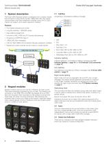
Eaton E31 keypad modules Technical Data TD07002003E Effective October 2012 1 System description The Eaton eSM hardware system is designed with a master module that connects to other ECUs via SAE J1939 CAN 2.0b. The master communicates with Eaton expansion modules using LIN 2.0. Each master can support up to seven expansion modules. Features • Four lighted indicators per switch • Long life switches: 1,000,000 cycles • Easy address assignment • Immune to SAE J1455 and J1113 power disturbances • Emissions to CISPR 25 Class 3 • J1939 CAN 2.0b messaging • LIN 2.0 / SAE J2602 communication between...
Open the catalog to page 2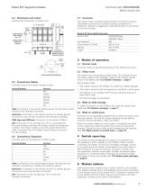
Eaton E31 keypad modules Technical Data TD07002003E Effective October 2012 2.7 Connector The system uses a standard sealed Deutsch DT Series connector. Using black connectors for masters and gray connectors for expansion modules is suggested to help identification of connectors on the wire harness. Deutsch DT Series Sealed Connector Connector body 6-pin wedge lock Female terminal 16-20 AWG Seal plug Crimper 2.5 Connections: Master The back cover of the master module is black. Terminal Number Function Vbat: Connection to the vehicle battery power. The Vbat pins of each connector are internally...
Open the catalog to page 3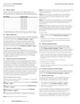
Eaton E31 keypad modules Technical Data TD07002003E Effective October 2012 5.1 Master address Master switch modules can have one of eight addresses. The address is stored in non-volatile memory. Master addresses are in the proprietary space of J1939 and have the following header values. Eaton Master Message Header The keypad address is stored permanently in non-volatile memory. It is set at the factory as A1 and can be changed by CAN message. 5.2 Master addressing The master address can be set by sending a "Set Master Address by CAN Message" command. All Eaton keypad masters on the CANbus will...
Open the catalog to page 4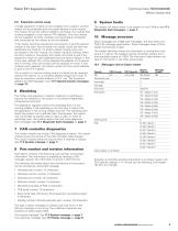
Eaton E31 keypad modules Technical Data TD07002003E Effective October 2012 5.8 Expansion service swap A single expansion module can be swapped into a system, and the master will automatically give the proper address to that module. The master will do this without CANbus command. The module that is being swapped in must have an FFh address. Only one module can be swapped. All other modules must be properly configured and connected for the master to set the address. If the master had three expansions connected to it and the second module in the chain was removed, the master would see that two expansions...
Open the catalog to page 5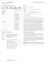
Eaton E31 keypad modules 10.2 Messages sent by Eaton master Transmission rate Data length Data page PDU format Source address Specific Address Length PDU specific On demand or on switch press 8 ~ _168 = Master 8 (A8h) _6_ 65,441 = Master 1 65,442 = Master 2 65,443 = Master 3 65,444 = Master 4 65,445 = Master 5 65,446 = Master 6 65,447 = Master 7 65,448 = Master 8 Same as PDU specific 10.3 CAN 2.0b 29 bit header Byte 0 bit 0 = Data page: This is not used, set to 0 bit 1 = Extended data page: not used, set to 0 bits 2...3 = Low order bits of the three bit priority bit 4 = High...
Open the catalog to page 6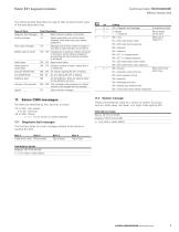
Eaton E31 keypad modules Technical Data TD07002003E Effective October 2012 What type of module it is The following table describes the type of data carried by each value of the data descriptor byte. Type of Data Data Descriptor Diagnostic fault messages 10h Report faults on modules in the system System messages 11h System commands sent to Eaton master. send data to other controllers on the vehicle Module types on master 18h.19h Configuration of expansion modules connected to the master. Used in address assignment and reporting the type of devices connected to the master Switch...
Open the catalog to page 7All Eaton Commercial Controls catalogs and technical brochures
 Toggle Switches
35 Pages
 Toggle switch accessories
4 Pages
 Rockers
104 Pages
 Eaton E32 3-switch modules
12 Pages
 Low voltage busway
49 Pages
 Electronic Products
17 Pages
 Dimmers and Wipers
6 Pages
 Special Devices
10 Pages
 Pushbuttons
23 Pages


Archived catalogs
 eMobility
25 Pages
 eMobility
56 Pages
 Buildings solutions
8 Pages
 Toggle Switches
29 Pages
 Pushbutton Switches
13 Pages
 Switches - 3100-3200 Series
4 Pages
 Switches - 1600-2600 Series
6 Pages
 Switches - 1500-2500 Series
4 Pages


- Single-pole switch
- Push-button switch
- Technology switch
- Multipole switch
- Electromechanical switch
- Safety electric switch
- Rotary electric switch
- Rocker switch
- IP67 switch
- Plastic switch
- Bipolar switch
- Hermetic switch
- Technology push-button switch
- Electromechanical push-button switch
- Illuminated switch
- AC electric switch
- On/off switch
- Lever switch
- DC switch
- Heavy-duty switch