- Catalogs
- EAO France
- Series 96: Audio and video
- Company
- Products
- Catalogs
- News & Trends
- Exhibitions
Series 96: Audio and video
1 /18Pages

Series 96: Audio and video
1 /18Pages
Catalog excerpts
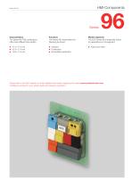
Market segments The Series 96 PCB pushbuttons offer three different lens widths: The Series 96 incorporates the following functions: The EAO Series 96 is especially suited for applications in the segment: Indicator Pushbutton Illuminated pushbutton Please refer to the EAO website to obtain detailed information regarding this series www.products.eao.com Congure a product to your exact needs and request a quotation.
Open the catalog to page 1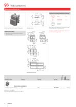
Equipment consisting of (schematic overview) Lens To obtain a complete unit, please select the red components from the pages shown. Additional Information Each Part Number listed below includes all the black components shown in the 3D-drawing. Product can differ from the current configuration. Illuminated pushbutton Snap-action switching element Contacts: C = Changeover The component layouts you will find from page 13 Wiring diagram Switching system Component layout
Open the catalog to page 4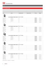
Lens standard single Switching action Lens standard single square, 17.4 x 17.4 mm Plastic black Plastic green Plastic grey Plastic white Lens standard single square, 17.4 x 17.4 mm Plastic black Plastic green Plastic grey Plastic white Plastic black Lens standard single square, 17.4 x 17.4 mm RAL 9011 Plastic green Plastic grey Plastic white Lens standard single square, 17.4 x 17.4 mm Plastic black Plastic green Plastic grey Plastic white Lens standard single square, 17.4 x 17.4 mm Plastic black Plastic green Plastic grey Plastic white Switching action: B = Momentary, C = Maintained
Open the catalog to page 6
Switching action Lens standard single square, 17.4 x 17.4 mm Plastic black Plastic green Plastic grey Plastic white Lens standard single rectangular, 14.8 x 17.4 mm Plastic black Plastic green Plastic grey Plastic white Plastic black Lens standard single rectangular, 14.8 x 17.4 mm RAL 9011 Plastic green Plastic grey Plastic white Lens standard single rectangular, 14.8 x 17.4 mm Plastic black Plastic green Plastic grey Plastic white Lens standard single rectangular, 14.8 x 17.4 mm Plastic black Plastic green Plastic grey Plastic white Switching action: B = Momentary, C = Maintained
Open the catalog to page 7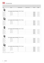
Switching action Lens standard single rectangular, 14.8 x 17.4 mm Plastic black Plastic green Plastic grey Plastic white Lens standard single rectangular, 14.8 x 17.4 mm Plastic black Plastic green Plastic grey Plastic white Plastic black Lens standard single rectangular, 12.4 x 17.4 mm RAL 9011 Plastic green Plastic grey Plastic white Lens standard single rectangular, 12.4 x 17.4 mm Plastic black Plastic green Plastic grey Plastic white Lens standard single rectangular, 12.4 x 17.4 mm Plastic black Plastic green Plastic grey Plastic white Switching action: B = Momentary, C = Maintained
Open the catalog to page 8
Switching action Lens standard single rectangular, 12.4 x 17.4 mm Plastic black Plastic green Plastic grey Plastic white Lens standard single rectangular, 12.4 x 17.4 mm Plastic black Plastic green Plastic grey Plastic white Plastic black Lens standard single rectangular, 12.4 x 17.4 mm RAL 9011 Plastic green Plastic grey Switching action Plastic white Lens standard single for film insert Lens standard single for film insert square, 17.4 x 17.4 mm Plastic black Plastic green Plastic grey Plastic white Lens standard single for film insert square, 17.4 x 17.4 mm Plastic black Plastic green Plastic...
Open the catalog to page 9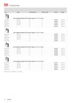
Switching action Lens standard single for film insert square, 17.4 x 17.4 mm Plastic black Plastic green Plastic grey Plastic white Lens standard single for film insert square, 17.4 x 17.4 mm Plastic black Plastic green Plastic grey Plastic white Plastic black Lens standard single for film insert square, 17.4 x 17.4 mm RAL 9011 Plastic green Plastic grey Plastic white Lens standard single for film insert square, 17.4 x 17.4 mm Plastic black Plastic green Plastic grey Plastic white Switching action: B = Momentary, C = Maintained
Open the catalog to page 10
Single-LED standard Additional Information • Without serie resistor, with special pin crank Operating voltage Operation current Single-LED standard Single-LED yellow Single-LED green
Open the catalog to page 11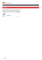
Lens remover
Open the catalog to page 12
Drawings Drilling plan (solder side) 4xØ1.0 for contacts trough-connection recommended trough-connection recommended Terminals (rear side) without trough-connection
Open the catalog to page 13
Technical data Snap-action switching element Switching system Environmental conditions Single-break, self-cleaning, snap-action switching element with tactile feel of operation. Lens Euro-Style ABS/PC or ABS, self-extinguishing Housing Polyester, self-extinguishing Shock resistance (single impacts, semi-sinusoidal) ≥30 g for 11 ms as per IEC 60512-4-3 Material of contact Gold-plated on nickel Mechanical characteristics Terminals PCB terminal Actuating force Actuating force 1.4 N ±0.3 N Actuating travel Lead distance 1.0 mm ±0.3 mm Total distance 1.7 mm ±0.5 mm Mechanical lifetime ≥5 million operations,...
Open the catalog to page 14
General notes 1. Engraving In addition to the most commonly used world languages, in DIN1451-3 close spacing, other typefaces are available as Scandinavian, Slavic, Greek, Russian and Polish. Red, blue and black lenses are filled with white colour. Other colour lenses are filled in black. Standard height of letters is 2 mm. If the height is not specified, we will supply 2 mm engraved letters. 2. Hot stamping On request. We will pleased to advise you. 3. Film inserts A speciallens, 17.4 x 17.4 mm, available for insertion of a colour foil or film. The film thickness is 0.2 mm. Lenses standard All...
Open the catalog to page 15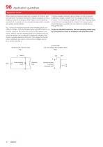
Application guidelines Suppressor circuits When switching inductive loads such as relays, DC motors, and DC solenoids, it is always important to absorb surges (e. g. with a diode) to protect the contacts. When these inductive loads are switched off, a counter emf can severely damage switch contacts and greatly shorten lifetime. Fig. 1 shows an inductive load with a free-wheeling diode connected in parallel. This free-wheeling diode provides a path for the inductor current to flow when the current is interrupted by the switch. Without this free-wheeling diode, the voltage across the coil will...
Open the catalog to page 16All EAO France catalogs and technical brochures
 data Series 17
1 Page
 BR45
BR4516 Pages
 The Human Touch®
17 Pages
 Series 57 - Indicator
4 Pages
 data Series 45
16 Pages
 data Series 04
13 Pages
 data Series 55
7 Pages
 Series 84. USB 3.0 Sockets.
2 Pages
 Emergency-Stop & Stop Switches
44 Pages
 Série 45
134 Pages
 Series 95: Audio and video
12 Pages
 Industrial Machinery
8 Pages
 Series 57: Public Transportation
16 Pages
 Series 10: Illumination
18 Pages
 Datasheet 82 Series
2 Pages
 Complete QuickSelector
188 Pages
 Transportation Products Catalog
128 Pages
 Audio Video Products Catalog
168 Pages


Archived catalogs

- Single-pole switch
- Push-button switch
- Technology switch
- Multipole switch
- Electromechanical switch
- Rotary electric switch
- Rocker switch
- IP67 switch
- LED indicator light
- Illuminated push-button switch
- Touch push-button switch
- Potentiometer
- Alarm sounder
- Action push-button switch
- Form push-button switch
- Metal switch
- IP65 push-button switch
- Plastic switch
- Manual potentiometer
- Momentary push-button switch