- Catalogs
- EAO France
- Series 95: Audio and video
- Company
- Products
- Catalogs
- News & Trends
- Exhibitions
Series 95: Audio and video
1 /12Pages

Series 95: Audio and video
1 /12Pages
Catalog excerpts

Market segments The Series 95 PCB pushbuttons can be used in combination with 1.5 to 2.5 mm PCBs. The buttons are selfattaching until they are soldered. Depending on the design, they can be equipped with 2 or 3 SMD LEDs. The series is available in the following sizes: The Series 95 incorporates the following functions: The EAO Series 95 is especially suited for applications in the segment: Pushbutton Illuminated pushbutton Please refer to the EAO website to obtain detailed information regarding this series www.products.eao.com Configure a product to your exact needs and request a quotation.
Open the catalog to page 1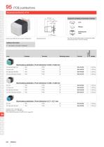
Equipment consisting of (schematic overview) Product can differ from the current configuration. Each Part Number listed below includes all the black components shown in the 3D-drawing. Additional Information • Lens plastic, colourless, transparent Component layout flat high gloss finished concave high gloss finished Switching action Illuminated pushbutton, Front dimension 19.05 x 19.05 mm Illuminated pushbutton, Front dimension 15.88 x 15.88 mm flat high gloss finished concave high gloss finished Illuminated pushbutton, Front dimension 12.7 x 12.7 mm flat high gloss finished Contacts: NO = Normally...
Open the catalog to page 4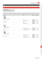
Additional Information • Lens plastic colourless, transparent flat high gloss finished flat high gloss finished Lens convexe (domed) mat convexe (domed) high gloss finished concave high gloss finished concave high gloss finished
Open the catalog to page 5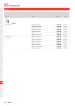
Plastic orange translucent Plastic yellow translucent Plastic green translucent Plastic blue translucent Plastic colourless transparent Plastic white translucent Plastic white translucent Plastic white translucent Plastic colourless transparent Plastic blue translucent Plastic green translucent Plastic yellow translucent Plastic red translucent Plastic orange translucent
Open the catalog to page 6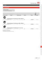
Rear side Switching element Additional Information Switching system Switching action Component layout • For combining with lens and diffuser Switching element, Front dimension 19.05 x 19.05 mm Slow-make switching element Switching element, Front dimension 15.88 x 15.88 mm Slow-make switching element Switching element, Front dimension 12.7 x 12.7 mm Slow-make switching element Contacts: NO = Normally open Switching action: B = Momentary The component layouts you will find from page 843
Open the catalog to page 7
Lens remover Additional Information • In case a lens gets damaged when being removed, it has to be replaced Lens remover Mounting tool
Open the catalog to page 8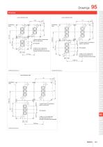
Drawings Layout (element side) Layout (element side) 13 Pushbutton base 2 holes "A" for contact pins final dimensions Ø 2.45 ± 0.07 through-connection recomended 4 support areas of pushbutton base on same level 4 support areas of pushbutton base on same level Pushbutton base 2 holes "A" for contact pins final dimensions Ø 2.45 ±0.07 through-connection recomended 51 Layout (element side) Pushbutton base 82 4 support areas of pushbutton base on same level 95 2 holes "A" for contact pins final dimension Ø 2.45 ± 0.07 through-connection recommended
Open the catalog to page 9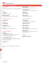
Technical data Pushbutton and Illuminated pushbutton Switching system Gold plated momentary contact, 1 normally open, self-cleaning Material Electric strength ≤ 50 mΩ, as per IEC 60512-2-2b at new state Isolation resistance > 1 TΩ, as per IEC 60512-2-3a between contacts Plastic parts PC, as per UL 94 HB, Cd-free Switch rating min. 1 mVDC, 100 μA max. 48 VDC, 50 mA Material of contacts CuSn, contact gold-plated, soldering terminal tinned Electric strength 2.5 kVAC, as per IEC 60512-2-11 Mechanical characteristics Environmental conditions Front protection IP 40 before front plate for complete switch...
Open the catalog to page 10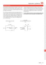
Application guidelines Suppressor circuits When switching inductive loads such as relays, DC motors, and DC solenoids, it is always important to absorb surges (e. g. with a diode) to protect the contacts. When these inductive loads are switched off, a counter emf can severely damage switch contacts and greatly shorten lifetime. Fig. 1 shows an inductive load with a free-wheeling diode connected in parallel. This free-wheeling diode provides a path for the inductor current to flow when the current is interrupted by the switch. Without this free-wheeling diode, the voltage across the coil will...
Open the catalog to page 11All EAO France catalogs and technical brochures
 data Series 17
1 Page
 BR45
BR4516 Pages
 The Human Touch®
17 Pages
 Series 57 - Indicator
4 Pages
 data Series 45
16 Pages
 data Series 04
13 Pages
 data Series 55
7 Pages
 Series 84. USB 3.0 Sockets.
2 Pages
 Emergency-Stop & Stop Switches
44 Pages
 Série 45
134 Pages
 Series 96: Audio and video
18 Pages
 Industrial Machinery
8 Pages
 Series 57: Public Transportation
16 Pages
 Series 10: Illumination
18 Pages
 Datasheet 82 Series
2 Pages
 Complete QuickSelector
188 Pages
 Transportation Products Catalog
128 Pages
 Audio Video Products Catalog
168 Pages


Archived catalogs

- Single-pole switch
- Push-button switch
- Technology switch
- Multipole switch
- Electromechanical switch
- Rotary electric switch
- Rocker switch
- IP67 switch
- LED indicator light
- Illuminated push-button switch
- Touch push-button switch
- Potentiometer
- Alarm sounder
- Action push-button switch
- Form push-button switch
- Metal switch
- IP65 push-button switch
- Plastic switch
- Manual potentiometer
- Momentary push-button switch