
Series 55 Swisstac: Public transportation, Machinery and Automation, Construction machines and specialpurpose vehicles, Lifting and moving, Panel building
120Pages
Catalog excerpts

Series Swisstac – Market segments The modular 16 mm Swisstac Series is particularly suited for: The series incorporates the following functions: The EAO Series Swisstac is especially suited for applications in the segments: Raised design PCB mounting The modular design of this series caters to a broad range of applications and combinations. Indicator Pushbutton Illuminated pushbutton E-STOP switch Stop switch Mushroom-head pushbutton Keylock switch Selector switch Buzzer Public transportation Machinery and Automation Construction machines and special-purpose vehicles Lifting and moving Panel building Please refer to the EAO website to obtain detailed information regarding this series www.products.eao.com Congure a product to your exact needs and request a quotation.
Open the catalog to page 1
Raised design Illuminated push-pull button 78
Open the catalog to page 3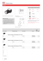
Raised design Equipment consisting of (schematic overview) Lens Product can differ from the current configuration. Dimensions [mm] L1 = Solder terminal 2.8 x 0.5 mm Fixing nut Lamp element block Additional Information • For the flush design please order the additional front bezel set, see chapter «Accessories» Each Part Number listed below includes all the black components shown in the 3D-drawing. • With IP 65 no anti-rotation device can be placed within the mounting cut-out. For rear-side mounting of the anti-rotation device, please see chapter «Accessories», Part No. 260-0020-00 or...
Open the catalog to page 4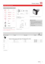
Raised design Equipment consisting of (schematic overview) Lens Pressure ring Sealing bulb Sealing ring Front bezel Dimensions [mm] L1 = Solder terminal 2.8 x 0.5 mm, PCB = Print terminal Product can differ from the current configuration. Additional Information • With IP 65 no anti-rotation device can be placed within the mounting cut-out. For rear-side mounting of the anti-rotation device, please see chapter «Accessories», Part No. 260-0020-00 or 260-0021-00 • Protection degree IP 40/IP 65 is determined by front bezel and lens Fixing nut Each Part Number listed below includes all the black...
Open the catalog to page 5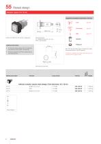
Raised design Equipment consisting of (schematic overview) Lens Front bezel Product can differ from the current configuration. Dimensions [mm] L1 = Solder terminal 2.8 x 0.5 mm, PCB = Print terminal Additional Information • For the flush design please order the additional front bezel set, see chapter «Accessories» Each Part Number listed below includes all the black components shown in the 3D-drawing. • Protection degree IP 40/IP 65 is determined by front bezel and lens To obtain a complete unit, please select the red components from the pages shown. Behind panel depth Lamp socket Wiring...
Open the catalog to page 6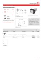
Raised design Equipment consisting of (schematic overview) Lens Front bezel page 101 Dimensions [mm] L1 = Solder terminal 2.8 x 0.5 mm, PCB = Print terminal Product can differ from the current configuration. Additional Information • For the flush design please order the additional front bezel set, see chapter «Accessories» Each Part Number listed below includes all the black components shown in the 3D-drawing. • With IP 65 no anti-rotation device can be placed within the mounting cut-out. For rear-side mounting of the anti-rotation device, please see chapter «Accessories», Part No....
Open the catalog to page 7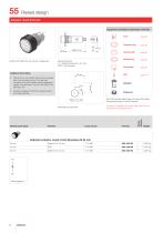
Raised design Equipment consisting of (schematic overview) Lens Pressure ring Sealing bulb Sealing ring Front bezel Product can differ from the current configuration. Dimensions [mm] L1 = Solder terminal 2.8 x 0.5 mm, PCB = Print terminal Additional Information • With IP 65 no anti-rotation device can be placed within the mounting cut-out. For rear-side mounting of the anti-rotation device, please see chapter «Accessories», Part No. 260-0020-00 or 260-0021-00 • Protection degree IP 40/IP 65 is determined by front bezel and lens Fixing nut Each Part Number listed below includes all the black...
Open the catalog to page 8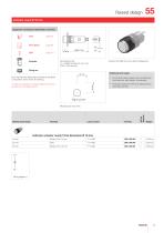
Raised design Equipment consisting of (schematic overview) Lens Front bezel Dimensions [mm] L1 = Solder terminal 2.8 x 0.5 mm, PCB = Print terminal Product can differ from the current configuration. Fixing nut Additional Information Each Part Number listed below includes all the black components shown in the 3D-drawing. • For the flush design please order the additional front bezel set, see chapter «Accessories» To obtain a complete unit, please select the red components from the pages shown. • Protection degree IP 40/IP 65 is determined by front bezel and lens Behind panel depth Lamp...
Open the catalog to page 9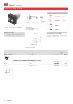
Raised design Equipment consisting of (schematic overview) Buzzer element L1 Front bezel Actuator Product can differ from the current configuration. Dimensions [mm] L1 = Solder terminal 2.8 x 0.5 mm, PCB = Print terminal Fixing nut Each Part Number listed below includes all the black components shown in the 3D-drawing. Additional Information • The buzzer 55 mm fits to the PCB plug-in base and multi plug housing To obtain a complete unit, please select the red components from the pages shown. Behind panel depth Wiring diagram Buzzer actuator square, Front dimension 24 x 24 mm
Open the catalog to page 10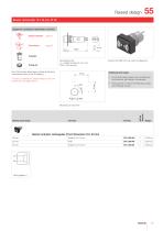
Raised design Equipment consisting of (schematic overview) Buzzer element Front bezel Dimensions [mm] L1 = Solder terminal 2.8 x 0.5 mm, PCB = Print terminal Each Part Number listed below includes all the black components shown in the 3D-drawing. Product can differ from the current configuration. Additional Information • For the flush design please order the additional front bezel set, see chapter «Accessories» To obtain a complete unit, please select the red components from the pages shown. • The buzzer 55 mm fits to the PCB plug-in base and multi plug housing Behind panel depth Wiring...
Open the catalog to page 11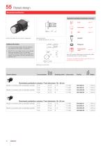
Raised design Illuminated pushbutton Equipment consisting of (schematic overview) Lens Front bezel Product can differ from the current configuration. Dimensions [mm] L1 = Solder terminal 2.8 x 0.5 mm, Additional Information • For the flush design please order the additional front bezel set, see chapter «Accessories» Switching element • With IP 65 no anti-rotation device can be placed within the mounting cut-out. For rear-side mounting of the anti-rotation device, please see chapter «Accessories», Part No. 260-0020-00 or 260-0021-00 Each Part Number listed below includes all the black...
Open the catalog to page 12All EAO France catalogs and technical brochures
-
data Series 17
1 Pages
-
BR45
16 Pages
-
The Human Touch®
17 Pages
-
Series 57 - Indicator
4 Pages
-
data Series 45
16 Pages
-
data Series 04
13 Pages
-
data Series 55
7 Pages
-
Series 84. USB 3.0 Sockets.
2 Pages
-
Emergency-Stop & Stop Switches
44 Pages
-
Série 45
134 Pages
-
Series 96: Audio and video
18 Pages
-
Series 95: Audio and video
12 Pages
-
Industrial Machinery
8 Pages
-
Series 57: Public Transportation
16 Pages
-
Series 10: Illumination
18 Pages
-
Datasheet 82 Series
2 Pages
-
Complete QuickSelector
188 Pages
-
Transportation Products Catalog
128 Pages
-
Audio Video Products Catalog
168 Pages


