
- Catalogs
- EAO France
- Series 31: Machinery and Automation, Panel building


Series 31: Machinery and Automation, Panel building

Series 31: Machinery and Automation, Panel building
Catalog excerpts

Market segments The compact 16 mm Series 31 is especially suited for: The Series 31 incorporates the following functions: The EAO Series 31 is especially suited for applications in the segments: Raised design PCB (with adaptor) This series is ideally suited for combined use with Series 51. Indicator Pushbutton Illuminated pushbutton Buzzer Machinery and Automation Panel building Please refer to the EAO website to obtain detailed information regarding this series www.products.eao.com Configure a product to your exact needs and request a quotation.
Open the catalog to page 1
Raised design
Open the catalog to page 3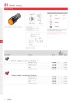
Raised design Equipment consisting of (schematic overview) Product can differ from the current configuration. Dimensions [mm] H = Universal terminal 2.0 x 0.5 mm, L = Solder terminal, L1 = Solder terminal 2.8 x 0.5 mm Each Part Number listed below includes all the black components shown in the 3D-drawing. To obtain a complete unit, please select the red components from the pages shown. Wiring diagram Component layout Indicator actuator, Front dimension 18 x 18 mm Indicator actuator, Front dimension 18 x 24 mm
Open the catalog to page 4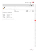
Wiring diagram Component layout Raised design Indicator actuator, Front dimension Ø 18 mm Solder 2.8 x 0.5 mm The component layouts you will find from page 23
Open the catalog to page 5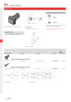
Raised design Equipment consisting of (schematic overview) Product can differ from the current configuration. Each Part Number listed below includes all the black components shown in the 3D-drawing. Dimensions [mm] L = Solder terminal, L1 = Solder terminal 2.8 x 0.5 mm Additional Information To obtain a complete unit, please select the red components from the pages shown. • Further information see «Technical data» Operating voltage Wiring diagram Buzzer, Front dimension 18 x 24 mm Plastic black Buzzer, Front dimension 18 x 24 mm Plastic black Continous tone Intermittent tone approx. 3 Hz Volume...
Open the catalog to page 6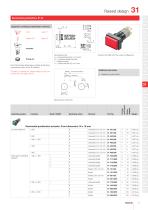
Raised design Equipment consisting of (schematic overview) Lens Dimensions [mm] H = Universal terminal 2.0 x 0.5 mm, H1 = Universal-Solder terminal, L = Solder terminal, L1 = Solder terminal 2.8 x 0.5 mm Fixing nut Each Part Number listed below includes all the black components shown in the 3D-drawing. To obtain a complete unit, please select the red components from the pages shown. 14 Product can differ from the current configuration. Additional Information • Material of contact Gold Switching action Switching system Component layout Illuminated pushbutton actuator, Front dimension 18 x 18 mm...
Open the catalog to page 7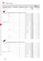
Raised design Snap-action switching element Switching action Switching system Wiring diagram Component layout Illuminated pushbutton actuator, Front dimension 18 x 24 mm Low-level element C Snap-action switching element Illuminated pushbutton actuator, Front dimension Ø 18 mm 1 NC Snap-action switching element Low-level element
Open the catalog to page 8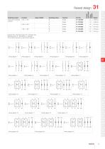
Raised design Contacts: NC = Normally closed, NO = Normally open Switching action: B = Momentary, C = Maintain The component layouts you will find from page 23 Wiring diagram 1 j Wiring diagram 2 j Wiring diagram 3 Wiring diagram 4 Wiring diagram 5 Wiring diagram 6 Wiring diagram 7 Wiring diagram < Wiring diagram 10 Wiring diagram 11
Open the catalog to page 9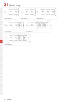
Raised design
Open the catalog to page 10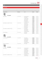
Lens plastic Product attribute yellow transparent green transparent orange translucent green translucent yellow transparent black opaque grey opaque colourless transparent green transparent white translucent flat, non-illuminative blue translucent yellow translucent flat, illuminative, less suitable for film insert blue transparent flat, illuminative, not suitable for film insert orange transparent smoked transparent red transparent flat, illuminative green transparent blue transparent concave, non-illuminative yellow transparent red transparent orange transparent concave, illuminative black...
Open the catalog to page 11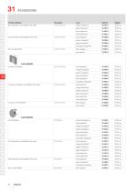
Product attribute flat, illuminative, not suitable for film insert yellow translucent green translucent blue translucent yellow transparent flat, illuminative, less suitable for film insert white translucent green transparent black opaque grey opaque flat, non-illuminative colourless transparent Lens plastic green transparent colourless transparent concave, illuminative, not suitable for film insert orange translucent green translucent yellow translucent blue transparent yellow transparent red transparent orange transparent concave, illuminative blue translucent white translucent black opaque...
Open the catalog to page 12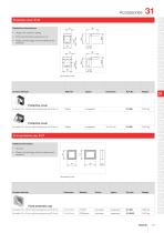
Protective cover, IP 40 Zusätzliche Informationen • Hinged, with means for sealing • Please note that bigger minimum distances are necessary • Front panel thickness reduces by 2 mm Product attribute Protective cover for button 18 x 18 mm with mounting cut-out Ø16 mm Protective cover for button 18 x 24 mm with mounting cut-out Ø16 mm Additional Information • Two-part • Please note that bigger minimum distances are necessary for button 18 x 18 mm with mounting cut-out Ø16 mm for button 18 x 24 mm with mounting cut-out Ø16 mm
Open the catalog to page 13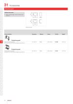
Protective guard Additional Information • Please note that bigger minimum distances are necessary Product attribute matt chrome matt chrome Protective guard narrow ends bent upwards, for button 18 x 24 mm with mounting cut-out Ø16 mm Protective guard broad sides bent upwards, for button 18 x 24 mm with mounting cut-out Ø16 mm
Open the catalog to page 14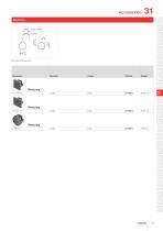
Blind plug Blind plug Blind plug Blind plug Plastic
Open the catalog to page 15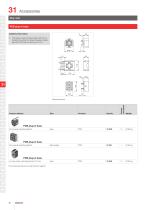
Rear side Additional Information • PCB plug-in base pins right-angle: With the extendable mounting the distance between plug-in base and PCB can be varied up to 3 mm Product attribute Component layout for low level switching element for low level switching element for snap-action switching element 2.8 mm The component layouts you will find from page 23
Open the catalog to page 16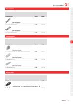
Flat receptacle Flat receptacle Flat receptacle Insulation sleeve Insulation sleeve cover plug-in terminals for snap-action switching element 2.8 mm Insulation sleeve Insulation sleeve Terminal cover Terminal cover for snap-action switching element 16
Open the catalog to page 17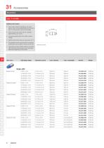
Additional Information • Due to high surface temperatures, the series resistor must not be soldered directly to the terminals of the equipment (use a terminal plate) • When using AC/DC types with AC operation, slight flickering can occure • Luminous intensity data of the LEDs on direct voltage • Electrical and optical data are measured at 25 °C • The specified versions are built with a protection diode (halve wave rectifier) in series and the LED • Luminosity and wave length variations caused by LED manufacturing processes may cause slight differences regarding the illumination Operating voltage...
Open the catalog to page 18All EAO France catalogs and technical brochures
 data Series 17
1 Page
 BR45
BR4516 Pages
 The Human Touch®
17 Pages
 Series 57 - Indicator
4 Pages
 data Series 45
16 Pages
 data Series 04
13 Pages
 data Series 55
7 Pages
 Series 84. USB 3.0 Sockets.
2 Pages
 Emergency-Stop & Stop Switches
44 Pages
 Série 45
134 Pages
 Series 96: Audio and video
18 Pages
 Series 95: Audio and video
12 Pages
 Industrial Machinery
8 Pages
 Series 57: Public Transportation
16 Pages
 Series 10: Illumination
18 Pages
 Datasheet 82 Series
2 Pages
 Complete QuickSelector
188 Pages
 Transportation Products Catalog
128 Pages
 Audio Video Products Catalog
168 Pages


Archived catalogs

- Power supply unit
- DC power supply
- AC/DC power supply
- Single-pole switch
- Push-button switch
- Technology switch
- Multipole switch
- Compact power supply
- Electromechanical switch
- Rotary electric switch
- Panel-mount keypad
- Rocker switch
- IP67 switch
- Programmable power supply
- LED indicator light
- Multiple-output power supply
- Regulated power supply
- Illuminated push-button switch
- Touch push-button switch
- Potentiometer