- Catalogs
- EAO France
- Series 14: Public transportation, Machinery and Automation, Construction machines and special-purpose vehicles, Lifting and moving, Panel building
- Company
- Products
- Catalogs
- News & Trends
- Exhibitions
Series 14: Public transportation, Machinery and Automation, Construction machines and special-purpose vehicles, Lifting and moving, Panel building
1 /64Pages

Series 14: Public transportation, Machinery and Automation, Construction machines and special-purpose vehicles, Lifting and moving, Panel building
1 /64Pages
Catalog excerpts

Market segments The compact 22.5 mm Series 14 enables space-saving installations and is especially suited for: The Series 14 incorporates the following functions: The EAO Series 14 is especially suited for applications in the segments: Flush design Raised design PCB (with adaptor) The low level switching element is laid out for low current applications. Indicator Pushbutton Illuminated pushbutton Mushroom-head pushbutton Keylock switch Selector switch Buzzer Public transportation Machinery and Automation Construction machines and special-purpose vehicles Lifting and moving Panel building Please refer to the EAO website to obtain detailed information regarding this series www.products.eao.com Configure a product to your exact needs and request a quotation.
Open the catalog to page 1
Flush design Raised design
Open the catalog to page 3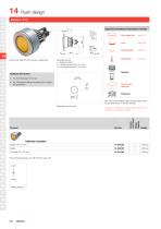
Flush design Equipment consisting of (schematic overview) Marking plate Product can differ from the current configuration. Dimensions [mm] L = Solder terminal, L1 = Solder terminal 2.8 x 0.5 mm, H = Universal terminal 2.0 x 0.5 mm Additional Information • For LED element fitting information see «Application guidelines» Part of front bezel set Each Part Number listed below includes all the black components shown in the 3D-drawing. To obtain a complete unit, please select the red components from the page s shown. Wiring diagram Component layout Indicator actuator The component layouts you will...
Open the catalog to page 4
Flush design Equipment consisting of (schematic overview) Pressure ring Product can differ from the current configuration. Additional Information Each Part Number listed below includes all the black components shown in the 3D-drawing. • Further information see «Technical data» 35 min. • The colour of anodized aluminium parts can vary due to technical production reasons Operating voltage Wiring diagram Buzzer, Front dimension Ø 35 mm Aluminium black anodized Aluminium natural anodiset
Open the catalog to page 5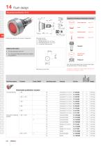
Flush design 14 Product can differ from the current configuration. Dimensions [mm] L = Solder terminal, L1 = Solder terminal 2.8 x 0.5 mm, H = Universal terminal 2.0 x 0.5 mm, H1 = Universal-Solder terminal Marking plate Equipment consisting of (schematic overview) Additional Information • For LED element fitting information see «Application guidelines» Part of front bezel set Each Part Number listed below includes all the black components shown in the 3D-drawing. To obtain a complete unit, please select the red components from the page s shown. Switching system Switching action Wiring diagram...
Open the catalog to page 6
Flush design Contacts: NC = Normally closed, NO = Normally open Switching action: B = Momentary, C = Maintain The component layouts you will find from page 291 Wiring diagram 1 Wiring diagram 2 Wiring diagram 3 Wiring diagram 5 Wiring diagram 6 Wiring diagram 10 Wiring diagram 11
Open the catalog to page 7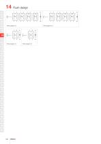
Flush design
Open the catalog to page 8
Flush design Equipment consisting of (schematic overview) Dimensions [mm] L = Solder terminal, L1 = Solder terminal 2.8 x 0.5 mm, H = Universal terminal 2.0 x 0.5 mm Marking plate 14 Product can differ from the current configuration. Additional Information Part of front bezel set • To obtain IP 67 use marking plate Part No. 704.609.9 Each Part Number listed below includes all the black components shown in the 3D-drawing. To obtain a complete unit, please select the red components from the page s shown. Switching action Wiring diagram Switching system Component layout Low-level element C Snap-action...
Open the catalog to page 9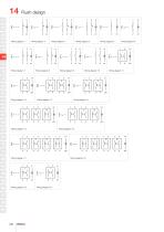
Flush design Wiring diagram 1 Wiring diagram 2 Wiring diagram 3 Wiring diagram 5 Wiring diagram 6 Wiring diagram 10 Wiring diagram 11
Open the catalog to page 10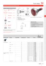
Flush design Illuminated mushroom head pushbutton, IP 67 1.5 ... 7 Equipment consisting of (schematic overview) Mushroom-head page 272 cap Marking plate Dimensions [mm] L = Solder terminal, L1 = Solder terminal 2.8 x 0.5 mm, H = Universal terminal 2.0 x 0.5 mm, H1 = Universal-Solder terminal 14 Product can differ from the current configuration. • For LED element fitting information see «Application guidelines» • To obtain IP 67 use marking plate Part No. 704.609.9 Part of front bezel set Each Part Number listed below includes all the black components shown in the 3D-drawing. Switching action...
Open the catalog to page 11
Flush design Contacts: NC = Normally closed, NO = Normally open Switching action: B = Momentary, C = Maintain The component layouts you will find from page 291 Wiring diagram 1 Wiring diagram 2 Wiring diagram 3 Wiring diagram 5 Wiring diagram 6
Open the catalog to page 12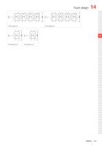
Flush design
Open the catalog to page 13
Flush design Keylock switch 2 positions, IP 65 Product can differ from the current configuration. Anti-twist ring Equipment consisting of (schematic overview) Dimensions [mm] L = Solder terminal, L1 = Solder terminal 2.8 x 0.5 mm, H = Universal terminal 2.0 x 0.5 mm • The standard lock: KABA 1001 • Two keys are supplied with each key lock switch Each Part Number listed below includes all the black components shown in the 3D-drawing. • Optional lock numbers on request Ø30.5 To obtain a complete unit, please select the red components from the page s shown. Switching positions (A = Rest, B = Momentary,...
Open the catalog to page 14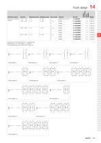
Flush design
Open the catalog to page 15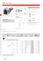
Flush design Selector switch 2 positions, IP 67 Product can differ from the current configuration. Anti-twist ring Equipment consisting of (schematic overview) Dimensions [mm] L = Solder terminal, L1 = Solder terminal 2.8 x 0.5 mm, H = Universal terminal 2.0 x 0.5 mm Part of front bezel set Each Part Number listed below includes all the black components shown in the 3D-drawing. To obtain a complete unit, please select the red components from the page s shown. Ø30.5 Switching system Switching action Wiring diagram Switching positions (A = Rest, B = Momentary, C = Maintained) Switching angle Component...
Open the catalog to page 16
Flush design
Open the catalog to page 17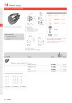
Raised design Indicator full face illumination, IP 67 14 Product can differ from the current configuration. Dimensions [mm] L = Solder terminal, L1 = Solder terminal 2.8 x 0.5 mm, H = Universal terminal 2.0 x 0.5 mm, H1 = Universal-Solder terminal Additional Information Equipment consisting of (schematic overview) • For LED element fitting information see «Application guidelines» • For front dimension Ø 29 mm Each Part Number listed below includes all the black components shown in the 3D-drawing. To obtain a complete unit, please select the red components from the page s shown. Wiring diagram...
Open the catalog to page 18All EAO France catalogs and technical brochures
 data Series 17
1 Page
 BR45
BR4516 Pages
 The Human Touch®
17 Pages
 Series 57 - Indicator
4 Pages
 data Series 45
16 Pages
 data Series 04
13 Pages
 data Series 55
7 Pages
 Series 84. USB 3.0 Sockets.
2 Pages
 Emergency-Stop & Stop Switches
44 Pages
 Série 45
134 Pages
 Series 96: Audio and video
18 Pages
 Series 95: Audio and video
12 Pages
 Industrial Machinery
8 Pages
 Series 57: Public Transportation
16 Pages
 Series 10: Illumination
18 Pages
 Datasheet 82 Series
2 Pages
 Complete QuickSelector
188 Pages
 Transportation Products Catalog
128 Pages
 Audio Video Products Catalog
168 Pages


Archived catalogs

- Single-pole switch
- Push-button switch
- Technology switch
- Multipole switch
- Electromechanical switch
- Rotary electric switch
- Rocker switch
- IP67 switch
- LED indicator light
- Illuminated push-button switch
- Touch push-button switch
- Potentiometer
- Alarm sounder
- Action push-button switch
- Form push-button switch
- Metal switch
- IP65 push-button switch
- Plastic switch
- Manual potentiometer
- Momentary push-button switch