- Catalogs
- EAO France
- Series 04: Public transportation, Machinery and Automation, Construction machines and special-purpose vehicles, Lifting and moving, Panel building
- Company
- Products
- Catalogs
- News & Trends
- Exhibitions
Series 04: Public transportation, Machinery and Automation, Construction machines and special-purpose vehicles, Lifting and moving, Panel building
1 /182Pages

Series 04: Public transportation, Machinery and Automation, Construction machines and special-purpose vehicles, Lifting and moving, Panel building
1 /182Pages
Catalog excerpts

Market segments The modular 22.5 mm Series 04 is especially suited for: The Series 04 incorporates the following functions: The EAO Series 04 is especially suited for applications in the segments: Flush design Raised design The modular design caters to a broad range of applications and combinations. Owing to its robust, user-friendly design, this series is ideally suited for rail vehicles. Indicator Pushbutton Illuminated pushbutton E-STOP switch Stop switch Mushroom-head pushbutton Key lock switch Key insert switch Selector switch Lever switch Public transportation Machinery and Automation Construction machines and special-purpose vehicles Lifting and moving Panel building Please refer to the EAO website to obtain detailed information regarding this series www.products.eao.com Congure a product to your exact needs and request a quotation.
Open the catalog to page 1
Flush design Selector rotary switch 50 Keylock rotary switch 52 Raised design Selector rotary switch 119
Open the catalog to page 3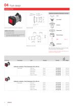
Flush design Equipment consisting of (schematic overview) Lens holder Product can differ from the current configuration. Dimensions [mm] Press frame Additional Information • Housing plastic black • The colour of anodized aluminium parts can vary due to technical production reasons 30 Bayonet flange Lamp block Mounting cut-outs [mm] Each Part Number listed below includes all the black components shown in the 3D-drawing. Plastic colourless Plastic yellow Plastic green Plastic blue Plastic colourless Indicator actuator, Front dimension 35 x 35 mm Plastic silver Indicator actuator, Front dimension...
Open the catalog to page 4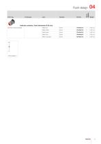
Plastic blue Plastic colourless Plastic green Front bezel Plastic yellow Front ring Wiring diagram Flush design Indicator actuator, Front dimension Ø 35 mm Aluminium natural anodized
Open the catalog to page 5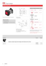
Flush design Equipment consisting of (schematic overview) Lens holder Actuator Product can differ from the current configuration. Dimensions [mm] X = Screw terminal Press frame • Housing plastic black Bayonet flange Lamp block • Other terminal options from the part lamp block see «Accessories» Mounting cut-outs [mm] PIT = Push-in terminal, P3 = Plug-in terminal 6.3 x 0.8 mm, P4 = Double plug-in terminal 6.3 x 0.8 mm, X = Screw terminal Each Part Number listed below includes all the black components shown in the 3D-drawing. To obtain a complete unit, please select the red components from the pages...
Open the catalog to page 6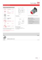
Flush design Equipment consisting of (schematic overview) page 128 Marking plate Dimensions [mm] X = Screw terminal Product can differ from the current configuration. Additional Information Part of front bezel set Lamp block Each Part Number listed below includes all the black components shown in the 3D-drawing. • Housing plastic grey Bayonet flange • Lens flat or raised possible; equal choose marking plate or marking cap • Other terminal options from the part lamp block see «Accessories» Mounting cut-outs [mm] PIT = Push-in terminal, P3 = Plug-in terminal 6.3 x 0.8 mm, P4 = Double plug-in terminal...
Open the catalog to page 7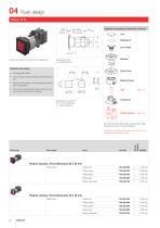
Flush design Equipment consisting of (schematic overview) Lens Marking foil Product can differ from the current configuration. Dimensions [mm] X = Screw terminal Press frame Bayonet flange • Other terminal options of the part flasher element see «Accessories» • The lamp block will be delivered with screw terminal • Housing plastic black • The colour of anodized aluminium parts can vary due to technical production reasons Lamp block Mounting cut-outs [mm] PIT = Push-in terminal, X = Screw terminal Flasher element Each Part Number listed below includes all the black components shown in the 3D-drawing....
Open the catalog to page 8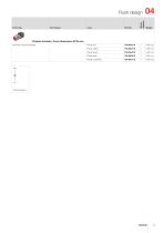
Front ring Front bezel Wiring diagram Flush design Flasher actuator, Front dimension Ø 35 mm Plastic red Plastic yellow Plastic green Aluminium natural anodized Plastic blue Plastic colourless
Open the catalog to page 9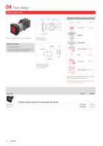
Flush design Equipment consisting of (schematic overview) Lens holder Actuator Product can differ from the current configuration. Dimensions [mm] X = Screw terminal Press frame • Housing plastic black Bayonet flange Flasher element Lamp block • Other terminal options from the part flasher element and lamp block see «Accessories» Mounting cut-outs [mm] PIT = Push-in terminal, X = Screw terminal Each Part Number listed below includes all the black components shown in the 3D-drawing. To obtain a complete unit, please select the red components from the pages shown. Front bezel Plastic black Plastic...
Open the catalog to page 10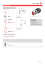
Flush design Equipment consisting of (schematic overview) Marking plate Dimensions [mm] X = Screw terminal Product can differ from the current configuration. Additional Information Part of front bezel set Lamp block Flasher element • Housing plastic grey Bayonet flange • Lens flat or raised possible; equal choose marking plate or marking cap • Other terminal options from the part flasher element and lamp block see «Accessories» Mounting cut-outs [mm] PIT = Push-in terminal, X = Screw terminal Each Part Number listed below includes all the black components shown in the 3D-drawing. To obtain a...
Open the catalog to page 11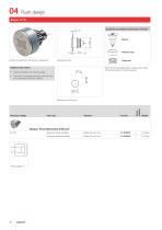
Flush design Equipment consisting of (schematic overview) Product can differ from the current configuration. Pressure ring Additional Information Each Part Number listed below includes all the black components shown in the 3D-drawing. • Further information see «Technical data» • The colour of anodized aluminium parts can vary due to technical production reasons Aluminium black anodized Aluminium natural anodized Operating voltage Wiring diagram Buzzer, Front dimension Ø 35 mm 24 VDC
Open the catalog to page 12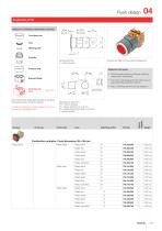
Flush design Equipment consisting of (schematic overview) Lens Marking plate 2 ... 6 Actuator Dimensions [mm] X = Screw terminal Product can differ from the current configuration. Pressure ring Plastic black Mounting cut-outs [mm] PIT = Push-in terminal, P3 = Plug-in terminal 6.3 x 0.8 mm, P4 = Double plug-in terminal 6.3 x 0.8 mm, X = Screw terminal Front bezel Switching action Wiring diagram To obtain a complete unit, please select the red components from the pages shown. Front ring • Max. 3 switching elements can be clipped on Each Part Number listed below includes all the black components...
Open the catalog to page 13All EAO France catalogs and technical brochures
 data Series 17
1 Page
 BR45
BR4516 Pages
 The Human Touch®
17 Pages
 Series 57 - Indicator
4 Pages
 data Series 45
16 Pages
 data Series 04
13 Pages
 data Series 55
7 Pages
 Series 84. USB 3.0 Sockets.
2 Pages
 Emergency-Stop & Stop Switches
44 Pages
 Série 45
134 Pages
 Series 96: Audio and video
18 Pages
 Series 95: Audio and video
12 Pages
 Industrial Machinery
8 Pages
 Series 57: Public Transportation
16 Pages
 Series 10: Illumination
18 Pages
 Datasheet 82 Series
2 Pages
 Complete QuickSelector
188 Pages
 Transportation Products Catalog
128 Pages
 Audio Video Products Catalog
168 Pages


Archived catalogs

- Single-pole switch
- Push-button switch
- Technology switch
- Multipole switch
- Electromechanical switch
- Rocker switch
- IP67 switch
- LED indicator light
- Illuminated push-button switch
- Touch push-button switch
- Potentiometer
- Alarm sounder
- Action push-button switch
- Form push-button switch
- Metal switch
- IP65 push-button switch
- Plastic switch
- Manual potentiometer
- Momentary push-button switch