
- Catalogs
- EAO France
- Audio Video Products Catalog


Audio Video Products Catalog

Audio Video Products Catalog
- Description: High-quality switches with options for illuminated and non-illuminated pushbuttons, suitable for professional audio and video applications. They support up to 3 colors per button using SMD LEDs.
- Fitting and Mounting: Designed for PCB mounting with a thickness range of 1.5 to 2.5 mm. The maximum soldering temperature is 260°C for 5 seconds.
- Marking and Illumination: Options include printed or engraved diffusers, with potential visual differences due to LED manufacturing processes.
- Switching System: Gold plated momentary contact, normally open, self-cleaning.
- Material: Plastic parts are PC, Cd-free, with gold-plated CuSn contacts.
- Mechanical Characteristics: Actuating travel of 4.5 mm, force of 3 N, and a lifetime of over 5 million operations.
- Electrical Characteristics: Supports SMD-LEDs with a radiation angle of 120°, electric strength of ≤50 mΩ, and isolation resistance >1 TΩ.
- Environmental Conditions: Operating temperature from -25°C to +70°C, storage temperature from -40°C to +80°C, with IP 40 front protection.
1. Switching Point: 2.3 mm ±0.8 mm at operation.
2. Life Time: Over 5 million operations, compliant with IEC 60512-5-9a.
3. Electrical Characteristics:
- Recommended SMD-LED types: P-LCC package or similar, with a radiation angle of approximately 120°.
- Maximum of 2 SMD-LEDs for switch size 12.70 mm, and 3 for sizes 15.88 mm and 19.05 mm.
- Electric strength: ≤50 mΩ as per IEC 60512-2-2b.
- Isolation resistance: >1 TΩ as per IEC 60512-2-3a.
- Switch rating: Minimum 1 mVDC, 100 μA; Maximum 48 VDC, 50 mA.
- Electric strength: 2.5 kVAC as per IEC 60512-2-11.
4. Environmental Conditions:
- Front protection: IP 40 before front plate.
- Operating temperature: -25 °C to +70 °C.
- Storage temperature: -40 °C to +80 °C.
- Vibration resistance: 10 g, at 10 - 2000 Hz, 0.75 mm as per IEC 60512-4-4.
- Shock resistance: 50 g, 11 ms as per IEC 60512-4-3.
The series 97 includes indicators and illuminated pushbuttons with maintained and momentary actions, featuring one or two contacts that can be normally open, normally closed, or a combination. The front dimensions are 9 x 9 mm or 9 mm in diameter, with an option for an overhanging lens of 12.2 x 12.2 mm.
These pushbuttons can be soldered to a PCB, with a contact layout conforming to a 2.54 mm module. A centering pin ensures precise mounting. Post-soldering cleaning must prevent fluid ingress into the switch.
Lenses are available in various colors and materials, with options for translucent or transparent finishes. Illumination is provided by LED Bi-Pin T1 lamps, directly soldered onto the PCB. Variations in LED manufacturing may cause visual differences.
Essential accessories include lenses and single-LEDs, with specific part numbers for different configurations and colors.
The document details various components such as lens plates, marking plates, lens bezels, and single LEDs. Lens plates are available in different colors and materials, primarily plastic, and are used for film inserts or marking plates. The document specifies dimensions, types, and part numbers for each component.
Procedures:
Assembly instructions include the use of a lens remover tool and guidelines for mounting components like illuminated pushbuttons on printed circuit boards (PCBs). The document emphasizes the importance of precise alignment and securing components with screws.
Standards and Norms:
The document references several IEC standards for mechanical and electrical characteristics, including contact resistance, isolation resistance, and environmental conditions. It specifies compliance with IEC 60512 for mechanical lifetime and electrical life, and IEC 60529 for front protection.
Recommendations:
For marking, the document suggests engraving or hot stamping for larger series, with specific typefaces and letter heights. It also recommends using transparent film inserts for overhanging lenses instead of engraving.
Technical Data:
The switching system is designed for low power electronic circuits, featuring single-break momentary contacts with various configurations. Mechanical characteristics include an actuating force of 3.4 N and a mechanical lifetime of up to 5 million operations. Electrical characteristics highlight a contact resistance of ≤50 mΩ and an electrical life of ≥2 million operations.
Environmental Conditions:
Components are designed to operate within a storage temperature range of -40°C to +85°C and a service temperature range of -25°C to +65°C. They offer IP 40 front protection and are resistant to shock and vibration as per specified IEC standards.
Drawings and Layouts:
The document includes technical drawings and circuit layouts for various components, ensuring proper assembly and integration into systems.
The document describes a series of industrial actuators and pushbuttons designed for durability and versatility. The actuators are available in various configurations, including indicators, pushbuttons, and illuminated pushbuttons, with options for marked or unmarked versions. They are made from chemical-resistant materials and comply with IP 67 and IP 40 protection standards, making them suitable for industrial environments.
Mounting Instructions:
The actuators are designed for a standard 16 mm diameter mounting hole and are secured to the front panel with a fixing nut, with a maximum mounting torque of 50 Ncm. The switching element is mounted on the PCB independently of the actuator, using a matrix dimension of 2.54 mm. The mounting flange allows the PCB to snap onto the pre-assembled actuator, eliminating the need for further adjustments. The flange is fastened to the PCB with screws, independent of the actuator.
Lenses and Marking:
The actuators feature a flat front bezel with an integrated pressure plate made of UV-resistant TPE, available in various colors. Marking options include hot stamping, laser marking, and film inserts.
Illumination:
LEDs in colors such as blue, yellow, green, orange, red, and white provide illumination for the touch surfaces. Variations in luminosity and wavelength may occur due to LED manufacturing processes.
Cleaning and Maintenance:
Care must be taken during PCB cleaning to prevent cleaning fluids from penetrating the switch. The document also provides instructions for dismantling the mounting flange using a specific tool.
Product Information:
Details are provided for various product configurations, including part numbers and descriptions for illuminated pushbuttons, essential accessories, and mounting components. The document includes technical drawings and circuit diagrams for further reference.
The document outlines the specifications for various components used in electronic assemblies, including LEDs, pushbuttons, and actuators. It specifies the operating voltage and current for single, bi-colour, and multi-LEDs, with details on light colors and type numbers. The document also provides material specifications for lenses, front bezels, frames, and switching elements, highlighting the use of polycarbonate, thermoplastic elastomer, and gold for contacts.
Procedures:
Instructions are provided for fitting components, emphasizing the need for a clean, grease-free panel back. The document advises on the use of series resistors for LEDs and provides guidelines for assembling PCB-mounted illumination and switching elements.
Technical Drawings:
Component layouts, technical drawings, and circuit diagrams are referenced, indicating their importance in the assembly process. These drawings are essential for understanding the spatial arrangement and connections of components.
Standards and Norms:
The document adheres to various IEC standards, such as IEC 60068-2-20 for soldering heat resistance and IEC 60512 for mechanical and electrical characteristics. It specifies environmental conditions, including storage and operating temperatures, and protection ratings (IP 40 and IP 67).
Recommendations:
For switching inductive loads, the document recommends using a free-wheeling diode to protect switch contacts from counter electromotive force (emf). It provides guidance on selecting diodes based on reverse breakdown voltage and forward current requirements.
Key Data from Tables and Figures:
The document includes tables listing type numbers, dimensions, and electrical characteristics of components. Figures illustrate the use of suppressor circuits with inductive loads, emphasizing the importance of diode placement to prevent voltage spikes.
Critical Information:
Attention is drawn to the need for selecting appropriate series resistors for LEDs and ensuring proper diode selection for inductive load protection. The document also highlights the importance of adhering to specified torque values and environmental conditions to ensure component longevity and reliability.
The document outlines specifications for various components including lenses, blind plugs, and LEDs. Lenses are available in multiple colors and sizes, with specific RAL color codes provided. Blind plugs are also detailed with dimensions and color options. LEDs are specified with operating voltage and current requirements, available in standard and Euro styles.
Technical Data:
The technical data section provides detailed information on the switching system, materials, mechanical and electrical characteristics, and environmental conditions. The switching system features a single-break, self-cleaning, snap-action element. Materials include ABS/PC or ABS for lenses and polyester for housing, both self-extinguishing. Mechanical characteristics include actuating force and travel, with a mechanical lifetime of over 5 million operations. Electrical characteristics cover contact resistance, isolation resistance, and electrical life, with specific standards referenced.
Environmental Conditions:
Components are designed to operate within a storage temperature range of -40°C to +85°C and a service temperature range of -25°C to +85°C. They offer IP67 front protection and are resistant to shock and vibration as per specified IEC standards.
Marking and Engraving:
The document details options for engraving and hot stamping, with standard letter heights and available typefaces. Film inserts are also discussed, with specifications for lens sizes and film thickness.
Assembly and Mounting:
Instructions for assembling and mounting devices are provided, including details on raised and flush mounting options. The document specifies the use of soldering terminals and provides dimensions for mounting holes.
Drawings and Diagrams:
Technical drawings and component layouts are included, providing visual guidance for assembly and installation. Circuit drawings are also referenced for further technical details.
General Notes:
The document includes general notes on product modifications and dimensions, emphasizing the right to modify technical data and the importance of adhering to specified dimensions.
The document outlines the specifications for various indicators and illuminated pushbutton actuators. These components are designed for use in electronic circuits with low power requirements. The indicators are available in different colors (green, red, yellow) and operate at voltages of 12 VDC, 2.2 VDC, and 24 VDC, with a current of 20 mA. The pushbutton actuators are available in both raised and flush mounting configurations, with options for normally closed (NC) and normally open (NO) contacts, and maintained or momentary action.
Materials:
The lenses are made from Polymethylacrylate (PMMA) and Polycarbonate (PC), while the contact material is gold on nickel plating. The actuator housing is made from black polyamide.
Mechanical Characteristics:
The terminals are suitable for soldering, with a maximum wire diameter of 2 x 0.5 mm². The actuating force is 1.4 N, with an actuating travel of 2.2 mm ±0.2 mm. The mechanical lifetime is 2 million cycles for momentary action and 1 million cycles for maintained action.
Electrical Characteristics:
The contact resistance is ≤100 mΩ, and the electrical life is ≥500,000 cycles at 30 VDC, 100 mA. The power consumption for the LED is 20 mA, with a switch rating of min. 10 μA at 100 μV and max. 100 mA at 42 VAC/VDC. The electric strength is 500 VAC, 50 Hz, for 1 minute between all terminals and earth.
Environmental Conditions:
The storage temperature ranges from -40 °C to +80 °C, and the service temperature is from -25 °C to +65 °C. The protection degree is IP 40 on the front side, with shock resistance of 50 g for 11 ms and vibration resistance of 10 g at 10-2000 Hz.
Accessories:
Essential accessories include lenses with and without LEDs, front bezel sets for flush mounting, and various mounting tools. The document also provides details on component layout, mounting dimensions, and technical drawings.
- Actuator Housing: Made of black polyamide.
- Terminals: Suitable for soldering, with a maximum wire diameter of 2 x 0.5 mm² and a maximum wire cross-section for stranded cable of 1 x 0.75 mm².
- Tightening Torque: Maximum of 20 Ncm for fixing nut.
- Actuating Force: 1.4 N.
- Actuating Travel: 2.2 mm ±0.2 mm.
- Rebound Time: ≤2.5 ms.
- Mechanical Lifetime: 2 million cycles for momentary action and 1 million cycles for maintained action, compliant with IEC 60512-5-9a.
- Contact Resistance: ≤100 mΩ initial value, as per IEC 60512-2-2b.
- Electrical Life: ≥500,000 cycles at 30 VDC, 100 mA, as per IEC 60512-5-9c.
- Power Consumption: LED consumes 20 mA.
- Switch Rating: Minimum 10 μA at 100 μV, maximum 100 mA at 42 VAC/VDC.
- Electric Strength: 500 VAC, 50 Hz, 1 min. between all terminals and earth, as per IEC 60512-2-11.
- Storage Temperature: -40 °C to +80 °C.
- Service Temperature: -25 °C to +65 °C.
- Protection Degree: IP 40 front side, as per IEC 60529.
- Shock Resistance: 50 g for 11 ms, as per IEC 60068-2-27.
- Vibration Resistance: 10 g at 10-2000 Hz, amplitude 0.75 mm, as per IEC 60512-4-4.
- The series includes indicators and illuminated pushbuttons with maintained and momentary action, featuring normally closed or open contacts.
- Front dimensions are 9 x 9 mm or 9 mm diameter.
- Mounting is possible from the front through the mounting hole, even with pre-attached wiring.
- Lenses are made of polycarbonate and available in various colors.
- Illumination is provided by filament lamps or LEDs in multiple colors.
- Various lenses and LED options are available for customization.
- PCB plug-in bases and flat receptacles are offered for different mounting configurations.
- Flat Receptacle: Type number 31-945 with an insulation sleeve 31-928.
- Illumination: Options include filament lamps and LEDs with various operating voltages and currents. Filament lamps have a maximum pin length of 5 mm, while LEDs have a maximum pin length of 8 mm for single LEDs and 5 mm for multi-LEDs.
- Materials: Contacts are gold or silver plated, with housings made from self-extinguishing materials like Polyetherimide (PEI) and Polyphenyleneoxide (PPO).
- Terminals support a maximum wire diameter of 2 x 0.8 mm and a wire cross-section of 1 x 0.75 mm².
- Actuating force is specified at 1.6 N with a travel of 2.8 mm ±0.2 mm.
- Mechanical lifetime is up to 5 million operations.
- Switch ratings vary based on plating, with maximum ratings of 50 VAC / 72 VDC, 0.8 A or 50 W for silver plated contacts.
- Electric strength is 2500 VAC, 50 Hz, for 1 minute between all terminals and earth.
- Storage temperature ranges from -40 °C to +85 °C.
- Service temperature varies with illumination type, with LEDs supporting up to +65 °C.
- Protection degree is IP 40 on the front side.
- Includes fixing nuts, dressing tools, lens removers, and mounting tools.
- Mounting instructions specify the use of a 22.5 mm diameter hole for actuators.
The document provides detailed technical specifications and assembly instructions for the Series 84 range of indicators, pushbuttons, and emergency-stop switches. These components are designed for industrial use, offering various configurations and mounting options.
Specifications
The Series 84 includes modular systems with lenses, actuators, and switching elements. They offer different front protection levels (IP 67, IP 65, IP 40) and are suitable for mounting on panels or PCBs. The emergency-stop pushbutton is foolproof, conforming to DIN EN ISO 13850 and EN IEC 60947 standards, with a single-piece design requiring no additional assembly.
Illumination
Switching elements can be equipped with integrated single LEDs in multiple colors. The series resistor is integrated, but variations in LED manufacturing may cause visual differences.
Mounting Instructions
Actuators are inserted into a 22.5 mm diameter hole, with switching units clipped to the rear. For PCB mounting, actuators are fixed to the board using a mounting flange. The document provides a recommended layout for uniform tactile switching.
Emergency-Stop Pushbutton
The emergency-stop pushbutton can be mounted on panels 1-4 mm thick, with a low behind-panel depth. It features a status indication ring and can be supplied with side-visible LED illumination.
Product Assembly
Details are provided for assembling indicators and pushbuttons with diameters of 25 mm and 40 mm, including components like lenses, marking plates, and sealing elements.
Accessories
Essential accessories include lens plastics, illumination elements, and mounting flanges. Customization options for flat ribbon cables and connectors are available upon request.
Technical Data
Technical drawings, circuit diagrams, and component layouts are referenced for further details on assembly and installation.
The document outlines the technical specifications for a switching system, including front panel thickness, mounting hole dimensions, terminal types, and mechanical and electrical characteristics. The front panel thickness ranges from 1 to 4 mm, with specific requirements for emergency-stop protective shrouds. The mounting hole is 22.5 mm in diameter, complying with EN IEC 60947-5-1 standards.
Mechanical Characteristics:
The system features soldering terminals and flat ribbon cables, with a tightening torque for the fixing nut at 80 Ncm. The actuating force is specified at 22 N ±4 N, with an actuating travel of approximately 4 mm. The mechanical lifetime is rated at over 50,000 cycles of operations.
Electrical Characteristics:
The devices comply with several standards, including EN IEC 60947-5-1 and EN IEC 60947-5-5. The rated operational voltage is 250 VAC, with a rated insulation voltage of 250 V and a rated impulse withstand voltage of 2.5 kV. Contact resistance in a new state is ≤ 50 mΩ, and isolation resistance is >1011 Ω at 500 VDC.
Environmental Conditions:
The storage temperature ranges from -25 °C to +80 °C, while the operating temperature is from -25 °C to +65 °C. The front protection is rated at IP 65.
Emergency-Stop Specifications:
The emergency-stop operation voltage ranges from 5 VDC to 30 VDC, with current consumption between 9.7 mA and 12.4 mA. The system supports various voltage and current combinations for different operational cycles.
Shock and Vibration Resistance:
The system is designed to withstand shock resistance up to 150 m/s² and vibration resistance up to 50 m/s², complying with EN IEC 60068-2 standards.
Material and Construction:
The connection cable is made of polyvinylchloride (PVC), and the contact material is a silver alloy gold plated. The switching element is constructed from thermoplastic polyester and polyacetal.
Application Guidelines:
The document provides guidelines for switching inductive loads, emphasizing the importance of using a free-wheeling diode to protect contacts from counter electromotive force (emf). Diagrams illustrate the setup for effective protection.
Drawings and Component Layout:
The document includes detailed drawings and component layouts for emergency-stop pushbuttons and illumination elements, with specific drilling plans for PCB mounting.
Catalog excerpts

EAO – Your Expert Partner for Human Machine Interfaces EAO Product Information Audio Video www ao.com/av_en .e
Open the catalog to page 1
Bringing pictures, sounds and stages to live For more than 60 years, EAO has been one of the leading suppliers of switches and indicators for audio/video, lighting and production equipment. No wonder many of the world’s best manufacturers use our products in their systems. Our customers not only appreciate the longevity and high quality but also the fair price policy. This has made us the No. 1 A/V switch supplier worldwide. EAO is relied on to help millions of listeners, viewers and audiences enjoy broadcasts of the F1 World Championship, Grand Slam finals and Olympic Games as well as some of...
Open the catalog to page 2
95 Description Product Information General notes The Series 95 is a high quality switch range containing illuminated and non-illuminated pushbuttons for professional Audio and Video applications. According to the switch version, the pushbuttons may be equipped with 2 or 3 SMD LED's with PLCC housing (height 2.1 mm) with a radiation angle of approx. 120 ° and thus generate up to 3 different colors on one pushbutton. The lenses are available matt translucent or clear transparent in flat, concave or convex form. Fitting The pushbutton should be plugged-in to the mounting hole and soldered onto the...
Open the catalog to page 7
95 Product Assembly Pushbutton illuminative 1 Lens 2 Diffuser 3 Switching element 0 8 05.2008 8
Open the catalog to page 8
95 PCB Pushbuttons Illuminated pushbutton Switching action Terminals IP 40 1 NO M P mat IP 40 high gloss finished mat high gloss finished mat IP 40 IP 40 1 NO 1 NO 1 NO M M M P P P IP 40 1 NO M P IP 40 1 NO M P Technical drawing Contacts Illuminated pushbutton high gloss finished Lens Plastic colourless transparent concave Plastic colourless transparent flush Plastic colourless transparent concave Plastic colourless transparent convex Plastic colourless transparent concave Plastic colourless transparent flush Plastic colourless transparent concave Plastic colourless transparent flush Plastic...
Open the catalog to page 9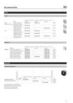
95 Accessories Front Lens Continuation see next page b 19.05 x 19.05 mm b 15.88 x 15.88 mm b 12.7 x 12.7 mm Lens high gloss finished mat Lens Plastic colourless transparent concave Plastic colourless transparent convex Plastic colourless transparent flush Plastic colourless transparent concave Plastic colourless transparent convex Plastic colourless transparent flush Typ-Nr. 95-704.770 Typ-Nr. 95-705.770 Typ-Nr. e 0.001 95-704.760 0.001 95-704.750 95-703.750 0.001 95-704.740 95-705.740 0.001 95-704.730 95-705.730 0.001 95-704.720 95-705.720 95-703.720 0.001 Diffuser Continuation see next page...
Open the catalog to page 10
95 Accessories > Assembling Lens remover Continuation see next page Lens remover e Typ-Nr. 95-900.005 0.003 Typ-Nr. 95-900.009 0.003 Owing to possible mechanical damage removed lens must be replaced by a new part Mounting tool Continuation see next page Mounting tool e 11 05.2008 11
Open the catalog to page 11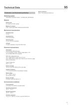
95 Technical Data Pushbutton- and Illuminated pushbutton Shock resistance 50 g, 11 ms, as per IEC 60512-4-3 Switching system Gold plated momentary contact, 1 normally open, self-cleaning Material Plastic parts PC, as per UL 94 HB, Cd-free Material of contacts CuSn, contact gold-plated, soldering terminal tinned Mechanical characteristics Actuating travel 4.5 mm Actuating force 3 N to end position Switching point 2.3 mm ±0.8 mm at operation Life time >5 million operations, as per IEC 60512-5-9a Electrical characteristics Illumination recommended SMD-LED types: P-LCC package or similar, radiation...
Open the catalog to page 12
Component layout 1 Illuminated pushbutton page 9 | Switching element page 10 4 support areas of pushbutton base on same level 2 holes "A" for contact pins Through-connection recommended Libraries for the PCB layout-system p-cad 200X see : www.pcad.com/recources/libraries Third-party Libraries 2 Illuminated pushbutton page 9 | Switching element page 10 2 holes "A" for contact pins Through-connection recommended Libraries for the PCB layout-system p-cad 200X see : www.pcad.com/recources/libraries Third-party Libraries
Open the catalog to page 13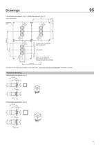
3 Illuminated pushbutton page 9 | Switching element page 10 4 support areas of pushbutton base on same level 2 holes "A" for contact pins Through-connection recommended Libraries for the PCB layout-system p-cad 200X see : www.pcad.com/recources/libraries Third-party Libraries
Open the catalog to page 14
97 Description Product Information General notes The series 97 contains indicators and illuminated pushbuttons with maintained and momentary action with one or two contacts which may be either normally open or normally closed or a combination of the two. The illuminated pushbuttons are equipped with the low-level switching system. The front dimensions are 9 x 9 mm or 9 mm dia.; or with overhanging lens 12.2 x 12.2 mm. Mounting The illuminated pushbuttons of series 97 can be soldered to a printed circuit board. The contact layout conforms to the module of 2.54 mm (1/10 "). A centering pin ensures...
Open the catalog to page 19
97 Product Assembly Pushbutton illuminative 1 2 3 4 0 Lens plate Marking plate Lens bezel Switching element 20 08.2008 20
Open the catalog to page 20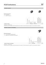
97 PCB Pushbuttons Indicator actuator Essential Accessories: d Lens page 24 d Single-LED page 25 Typ-Nr. 97-081.007 Typ-Nr. 97-061.007 Circuit drawing P Technical drawing IP 40 Mounting dimensions Terminals Indicator actuator b 9 x 9 mm Ø 9 mm Component layout Front protection Continuation see next page e 1 1 1 1 0.002 Terminals: P = PCB terminal Component layout from page 28, Mounting dimensions from page 28, Technical drawing from page 29, Circuit drawing from page 29 Indicator actuator overhanging Essential Accessories: d Lens overhanging complete page 24 d Single-LED for overhanging version...
Open the catalog to page 21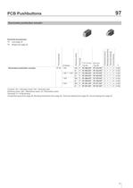
97 PCB Pushbuttons Illuminated pushbutton actuator Essential Accessories: d Lens page 24 d Single-LED page 25 Typ-Nr. 97-372.037 97-332.037 97-373.037 97-333.037 97-370.037 97-330.037 97-371.037 97-331.037 Circuit drawing 2 NO Typ-Nr. 97-382.037 97-352.037 97-383.037 97-353.037 97-380.037 97-350.037 97-381.037 97-351.037 Technical drawing 1 NO P P P P P P P P Mounting dimensions 1 NC + 1 NO MA M MA M MA M MA M b 9 x 9 mm Ø 9 mm Component layout IP 40 Terminals Illuminated pushbutton actuator Contacts 1 NC Switching action Front protection Continuation see next page e 2 2 2 2 2 2 2 2 1 1 1 1 1...
Open the catalog to page 22All EAO France catalogs and technical brochures
 data Series 17
1 Page
 BR45
BR4516 Pages
 The Human Touch®
17 Pages
 Series 57 - Indicator
4 Pages
 data Series 45
16 Pages
 data Series 04
13 Pages
 data Series 55
7 Pages
 Series 84. USB 3.0 Sockets.
2 Pages
 Emergency-Stop & Stop Switches
44 Pages
 Série 45
134 Pages
 Series 96: Audio and video
18 Pages
 Series 95: Audio and video
12 Pages
 Industrial Machinery
8 Pages
 Series 57: Public Transportation
16 Pages
 Series 10: Illumination
18 Pages
 Datasheet 82 Series
2 Pages
 Complete QuickSelector
188 Pages
 Transportation Products Catalog
128 Pages


Archived catalogs

- Power supply unit
- DC power supply
- AC/DC power supply
- Single-pole switch
- Push-button switch
- Technology switch
- Multipole switch
- Compact power supply
- Electromechanical switch
- Rotary electric switch
- Panel-mount keypad
- Rocker switch
- IP67 switch
- Programmable power supply
- LED indicator light
- Multiple-output power supply
- Regulated power supply
- Illuminated push-button switch
- Touch push-button switch
- Potentiometer