- Catalogs
- E2 Systems
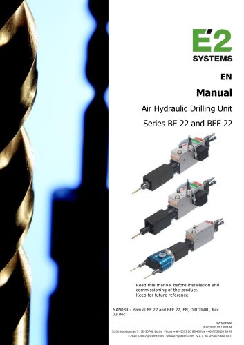
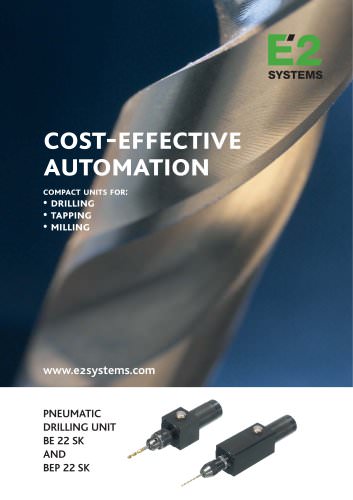
- Series BE 22 and BEF 22
Series BE 22 and BEF 22
1 /23Pages
Series BE 22 and BEF 22
1 /23Pages
Catalog excerpts
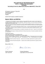
DECLARATION OF INCORPORATION OF PARTLY COMPLETED MACHINERY ORIGINAL According to the EC's Machinery Directive 2006/42/EC, Annex 2B We, E2 Systems a division of Tubex AB Strömslundsgatan 3 507 62 Borås Sweden, declare that the partly completed machinery: Model: BE22x and BEF22x * Is designed to be embedded in a larger machinery or assembled with another machine, which together will constitute machinery covered by Directive 2006/42/EC "Machinery Directive" and which shall be constructed in compliance with this directive, and * Must not be put into service until the machinery, which the partly completed...
Open the catalog to page 3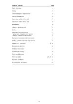
Table of content: Page: Information about manufacturer 6 Description of the drilling unit 7 Installation of the drilling unit 8 Mounting of cutting tools 9 Description of limit switches 11 - pneumatic, installation and function 11 - electric, installation and function 12 Example of connection with limit switch 13 Drilling unit with automatic chip removal 14 Spare parts drawing 19 Spare parts list 20, 21, 22
Open the catalog to page 4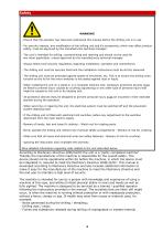
WARNING! - Ensure that the operator has read and understood this manual before the drilling unit is in use. - For security reasons, any modification of the drilling unit and it’s accessories, which may affect product safety, must be approved by the manufacturers technical manager. - The unit is intended for drilling, countersinking and reaming and should not be used for any other application, unless approved by the manufacturers technical manager - Always follow local security regulations regarding installation, operation and maintenance. - The drilling unit must be securely fixed and the installation...
Open the catalog to page 5
General recommendations - Apply a system for monitoring the tool in the machine. If no such system is at hand, we recommend user/operator to frequently control the tool. To ensure that no damages occurred. Thorough review of the unit Visual control of any external damages. Ensure there is possibility to quickly turn off the motor and air-supply and run a normal cycle without tool and material (to avoid further damages at the material and unit). Listen for noise from bearings and also control the run-out at the spindle nose. If not ok, unit has to be repaired and a new control for damages will...
Open the catalog to page 6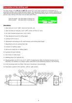
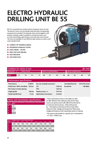
Description of the drilling unit The basic design of the BE 22 and BEF 22 consists of a vane motor powered by compressed air, a pneumatic cylinder, and a closed hydraulic system. The total stroke length can be variably subdivided into rapid advance and working feed across the whole range. The throttle/check valve in the hydraulic system permits exact setting of the feed rate and high speed return. Type and speed: See data label on drilling unit Serial number: See data label on drilling unit Description: 1. Main inlet port, G1/4'' (NPT). Direct air from FRL unit. 2. Start and feed air inlet port,...
Open the catalog to page 7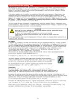
Installation of the drilling unit This Drilling and Tapping Unit is only intended for use in machinery which applies to the Machine Directive 2006/42/EC. This Drilling and Tapping Unit is designed for normal drilling, countersinking, reaming and tapping. In applications requiring high-precision hole placement or when drilling into rounded or slanted surfaces, drill bushings must be used. To be able to use the unit, it must first be installed and fitted with control equipment. Regardless of how simple the installation is performed, the unit must be fitted with necessary protective devices to avoid...
Open the catalog to page 8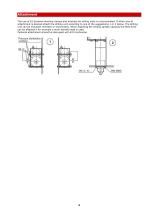
Attachment The use of E2 Systems monting clamps and brackets for driling units is recommended. If other way of attachment is desired attach the drilling unit according to one of the suggestions 1 or 2 below. The drilling unit can be mounted vertically or horizontally. When attaching the drilling spindle upwards the feed force can be affected if for example a multi-spindle head is used. Optional attachment should be discussed with E2's technician.
Open the catalog to page 9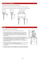
Mounting of cutting tools The following cutting tools can be used with drilling unit: Drills, hole saws, core drills, shank end mills, countersinkers, reamers or broaches. The drilling unit can be fitted with either key chuck, collet chuck or multi-spindle head. Key Chuck: Collet Chuck: Multi-spindle head: Setting 1. Ensure that the FRL unit is working properly. 2. Check the oil-level indicator (10). (See Maintenance instruction) 3. The desired drilling depth is set with adjusting screw (4). One revolution on the adjusting screw is 1 mm (.039 In). Screwed in adjusting screw provides a short drilling...
Open the catalog to page 10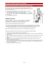
Description of limit switches, accessories Drilling unit BE 22 and BEF 22 with pneumatic limit switch The limit switch unit (micro-valves) is preset and operates independently of the set drilling depth. If the drilling depth is changed, resetting of micro-valves V3 and V4 is not necessary. 16. 3 pcs air hoses, Polyamide Ø 4/2,7 mm (5/32'') and 1 pce Y-coupling. 17. 2 pcs pneumatic micro-valves (3-way), normally closed. V3 = outer micro-valve, actuated in rear spindle position = home position. V4 = inner micro-valve, actuated in front spindle position = return position. 18. 2 pcs Cams. 19. 1 pce...
Open the catalog to page 11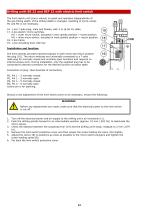
Drilling unitt BE 22 and BEF 22 with electric limit switch The limit switch unit (micro-valves) is preset and operates independently of the set drilling depth. If the drilling depth is changed, resetting of micro-valves M1 and M2 is not necessary. 16. 1 pce 7-pole plug, male and female, with 2 m (6.56 Ft) cable. 17. 2 pcs electric micro-switches. M1 = outer micro-switch, actuated in rear spindle position = home position. M2 = inner micro-switch, actuated in front spindle position = return position. 18. 2 pcs Cams. 19. 1 pce Actuating lever with bar. Installation and function: The limit swiches...
Open the catalog to page 12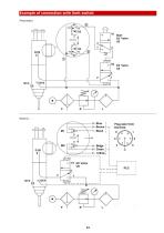
Example of connection with limit switch Pneumatic:
Open the catalog to page 13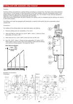
Function. First the drilling unit performs a partial drilling according to a preset time. The feed is then interrupted for chip removal, I e the spindle is returning quickly to the home position and then immediately starts a new partial drilling with rapid feed to the previous drilling depth, etc. The number of chip removal operations depends on the combination of working feed rate and time. When the preset drilling depth has been reached, the drilling cycle is completed and the drilling unit returns to the home position. The drilling unit must be equipped with pneumatic or electric limit switch...
Open the catalog to page 14All E2 Systems catalogs and technical brochures
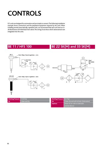 Controls
5 Pages
 Tool Holders
3 Pages
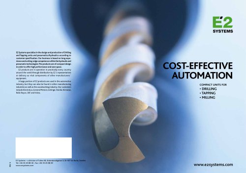
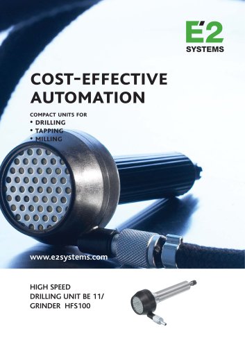
 Cpst-effective Automation
6 Pages
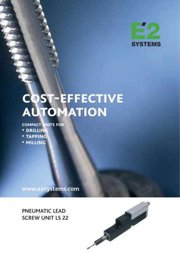 Cost-effective Automation
4 Pages
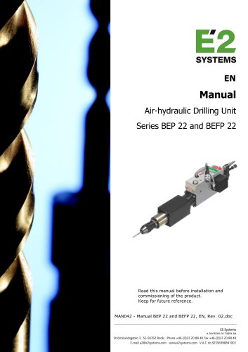 Series BEP 22 and BEFP 22
23 Pages
 Series BE 21
19 Pages
 Series BE 22 SK
15 Pages
 E2-catalog
30 Pages


- Drilling chuck
- Motorized spindle
- Drill chuck
- Pneumatic spindle
- Tapping spindle
- Pneumatic drilling unit
- High-speed pneumatic spindle
- Key type drill chuck
- Electric drilling unit
- Hydraulic drilling unit
- Milling pneumatic spindle
- Single-spindle drilling unit
- Multi-spindle tapping unit
- Multi-spindle drilling unit
- Multi spindle
- Electro-pneumatic drilling unit