
- Catalogs
- E2 Systems
- Controls

Controls
Controls
Catalog excerpts

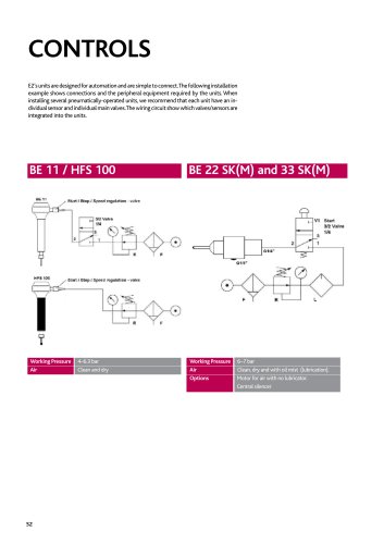
controls E2’s units are designed for automation and are simple to connect.The following installation example shows connections and the peripheral equipment required by the units. When installing several pneumatically-operated units, we recommend that each unit have an individual sensor and individual main valves.The wiring circuit show which valves/sensors are integrated into the units. Working Pressure 4–6.3 bar Working Pressure Air Clean and dry Air Options 6–7 bar Clean, dry and with oil mist (lubrication). Motor for air with no lubricator. Central silen
Open the catalog to page 1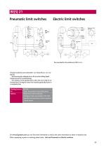
BE(S) 21 Pneumatic limit switches M1 Electric limit switches The limit switches come with either 1.2 m hose (Pn) or 1.2 m cable (El). We recommend a delayed return for accurate drilling depth tolerances and for countersinking. The rotation of the spindle starts when the unit is fed air for forward feed. During the return the rotation gradually slows to a complete stop. Working Pressure Air Options 6–7 bar Clean, dry and with oil mist (lubrication). Motor for air with no lubricator. Emergency break valve parallel to M2, which stops the unit and returns it to home position. Central silencer On...
Open the catalog to page 2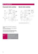
BE 22 and BE 33 Pneumatic limit switches Electric limit switches The limit switches comes with either 2 m hose (Pn) or 2 m cable (El). We recommend a delayed return for accurate drilling depth tolerances and for countersinking. When the main valve is actuated, spindle feed and rotation commence. When the valve is released, the spindle returns to its start position and the motor’s rotation ceases. Working Pressure Air Options 6–7 bar Clean, dry and with oil mist (lubrication). Motor for air with no lubricator. Emergency break valve parallel to M2, which stops the unit and returns it to home position....
Open the catalog to page 3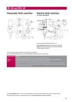
BE 48 and BEG 48 Pneumatic limit switches V5 Electric limit switches The max load for the switches at 220 V is 1A. Linear transducer (optional) for full control of the stroke. Ideal for the control of automatic chip removal, multiwall drilling, tapping, reaming etc. The limit switches comes with either 2 m hose (Pn) or 2 m cable (El). We recommend a delayed return for accurate drilling depth tolerances and for countersinking. Working Pressure Air Options Motor Max 8 bar Clean and dry. Lubrication is not necessary but increases the life span of the unit. Emergency break valve parallel to V4 (unit...
Open the catalog to page 4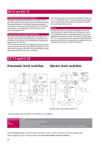
BE 55 and BEG 55 Control systems and electrical connections: The signal comes from the limit sensors of the BE(G) 55 from the control system. There is one sensor for the home and one for the extracted position. The drilling or tapping cycle/depth is controlled by a linear sensor which enables you to set the rapid feed distance, max drilling depth, chip-removal cycle and/or multi-wall drilling function. There are two control systems to choose from: C1A where you handle sensor signals and control valves externally (the control system has push buttons to manually control the valves for fast approach...
Open the catalog to page 5All E2 Systems catalogs and technical brochures
 Tool Holders
3 Pages
 Cpst-effective Automation
6 Pages
 Cost-effective Automation
4 Pages
 Series BEP 22 and BEFP 22
23 Pages
 Series BE 22 and BEF 22
23 Pages
 Series BE 21
19 Pages
 Series BE 22 SK
15 Pages
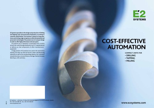 E2-catalog
30 Pages




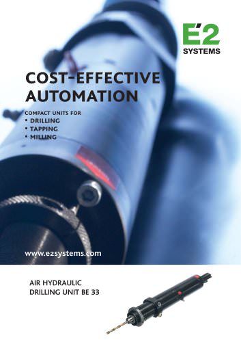
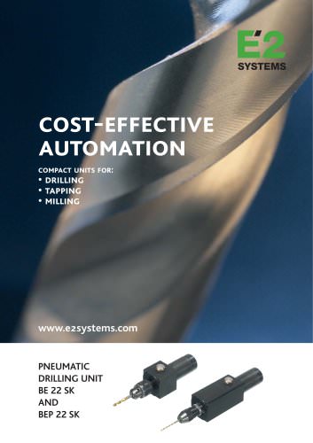
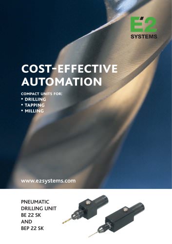
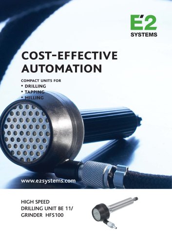
- Chuck
- Drilling chuck
- Motorized spindle
- Drilling unit
- Drilling spindle
- Drill chuck
- Pneumatic spindle
- Pneumatic drilling unit
- Tapping spindle
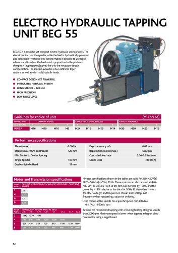
- Tapping unit
- Key type drill chuck
- High-speed pneumatic spindle
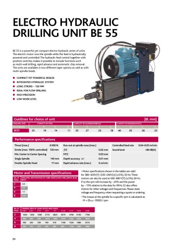
- Electric drilling unit
- Hydraulic drilling unit
- Milling pneumatic spindle
- Multi-spindle tapping unit
- Single-spindle drilling unit
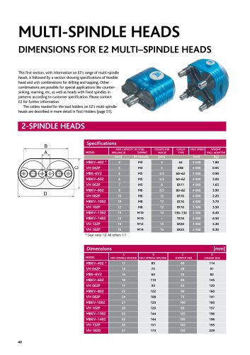
- Multi-spindle drilling unit
- Multi spindle
- Electro-pneumatic drilling unit