


- Products
- Catalogs
- News & Trends
- Exhibitions
1110

1110
Catalog excerpts
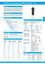
Thermal Overcurrent Circuit Breaker 1110-... Description Tease-free, trip-free, snap action mechanism. Designed for snap-in panel mounting utilising round hole or industry standard fuse-holder cut-out dimensions. Featuring an ergonomically styled two colour actuator with indicator band clearly showing the tripped/OFF position. Approved to CBE standard EN 60934 (IEC 60934): S-type TO CBE Typical applications Motors, transformers, solenoids, extra low voltage systems, household and office machines, instrumentation, marine applications, mobile homes. Ordering information Type No. 1110 snap in panel mounting Mounting F1 panel thickness 0.8...1.6 mm (.031 -.063 in) F2 panel thickness 1.8...3 mm (.071-.118 in) Number of poles 1 1-pole protected Actuator style 2 black push button/white indicator ring, push-push function Terminal design P1 blade terminals A6.3-0.8 (QC .250) Characteristic curve M1 medium delay Current ratings 0.05...16A For further details please see chapter: Technical Information Voltage rating AC 250 V; DC 50 V Current rating 0.05...16 A Typical life IN operations Un I 0.05...10 A Standard current ratings and typical internal resistance values Current rating (A) Ambient temperature -20...+60 °C (-4...+140 °F) Insulation co-ordination rated impulse pollution (IEC 60664 and 60664 A) withstand voltage degree 2.5 kV 2 reinforced insulation in operating area Dielectric strength (IEC 60664 and 60664A) test voltage operating area AC 3,000 V Insulation resistance > 100 MΩ (DC 500 V) Interrupting capacity Icn AC 250 V: 0,05...10 A 8 x IN DC 50 V: 0,05...6.5 A 10 x IN 7...16 A 130 A DC 28 V: 7...10 A 200 A Interrupting capacity IN UN (UL 1077/EN60934 PC 1) 0.05...6 A AC 250 V 1,000 A 7...16 A AC 125 V 1,000 A 0.05...16 A DC 50 V 1,000 A Degree of protection operating area IP40 (IEC 60529/DIN 40050) terminal area IP00 Vibration 8 g (57-500 Hz) ± 0.61 mm (10-57 Hz), to IEC 60068-2-6, test Fc, 10 frequency cycles/axis Shock 0 g (11 ms) 3 to IEC 60068-2-27, test Ea Corrosion 96 hours at 5 % salt mist, to IEC 60068-2-11, test Ka Humidity 240 hours at 95 % RH to IEC 60068-2-78, test Cab Mass approx. 12 g Standard current ratings (A) Preferred types Preferred types Technical data Approvals Standard Rated voltage Current ratings
Open the catalog to page 1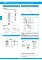
Thermal Overcurrent Circuit Breaker 1110-... Dimensions Internal connection diagram 1 Typical time/current characteristics at +23 °C/+73.4 °F black white When installing the circuit breaker apply pressure on bezel only. insertion force ≤ 20 N, removal force ≥ 120 N installation side installation side Trip time in seconds 16±0.15 .630±.006 insertion force ≤ 40 N, removal force ≥ 120 N The time/current characteristic curve depends on the ambient temperature prevailing. In order to eliminate nuisance tripping, please multiply the circuit breaker current ratings by the derating factor shown below....
Open the catalog to page 2All E-T-A catalogs and technical brochures
 REX12 Brochure
24 Pages
 MPR10, MPR20
5 Pages
 CATALOGUE
108 Pages
 CPC20
CPC2012 Pages
 CPC12
CPC128 Pages
 PC10IO
2 Pages
 PC10PN
4 Pages
 PC10PB
4 Pages
 SVS18
SVS186 Pages
 1140-E
4 Pages
 129-L11-H-KF
2 Pages
 127
1274 Pages
 104
1044 Pages
 PowerPlex® Power Module
8 Pages


- Single-pole switch
- Switching relay
- Technology switch
- Protection relay
- Electromechanical switch
- Solid state relay
- Current protection relay
- Current circuit breaker
- Voltage circuit breaker
- Single-pole circuit breaker
- Electric motor protection relay
- Thermal-magnetic circuit breaker
- DC solid state relay
- Overload relay
- Mini circuit breaker
- Manual reset circuit breaker
- Over-current protection relay
- Thermal circuit breaker
- Overload circuit breaker