- Catalogs
- E+E ELEKTRONIK
- Datasheet HTE501
Datasheet HTE501
1 /27Pages

Datasheet HTE501
1 /27Pages
Catalog excerpts
DatasheetHTE501 Digital Humidity and Temperature Sensor
Open the catalog to page 1
Datasheet HTE501 Introduction to the E+E Digital Humidity and Temperature Sensor HTE501 Digital Humidity and Temperature Sensor The next generation of digital RH/T sensor combines accuracy and reliability to meet the highest current and future requirements. The integrated constant current heater as well as the innovative and proven E+E proprietary coating ensures outstanding performance even in harsh environments. In a DFN package with a footprint of only 2.5 x 2.5 mm, the HTE501 provides an exceptional accuracy of up to ±1.8 %RH incl. hysteresis, paired with dew point calculation and a maximum...
Open the catalog to page 2
www.epluse.com v1.7 / Modification rights reserved | 3
Open the catalog to page 3
www.epluse.com v1.7 / Modification rights reserved | 4
Open the catalog to page 4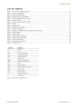
Table 1: List of HTE501 specific acronyms v1.7 / Modification rights reserved | 5
Open the catalog to page 5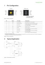
Bottom view Thermal pad internally connected to GND Figure 1: DFN8 pin configuration Serial data line for I2C communication Output open drain Indicates heater status and measurement invalid1) Input high-Z I2C device address pin, bit 1 of the 7 bit address; do not leave floating Serial clock line for I2C communication Input high-Z I2C device address pin, bit 2 of the 7 bit address; do not leave floating Input high-Z I2C device address pin, bit 3 of the 7 bit address; do not leave floating Ground (internally connected to thermal pad)2) 1) If unused see pin description (HI Pin). 2) S oldering of...
Open the catalog to page 6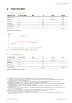
3 Specification 3.1 Relative Humidity Sensor Table 4: Temperature sensor parameters 1) In the periodic mode the humidity hysteresis is included. See also chapter 3.3 Recommended Operating Conditions. 2) In the periodic mode the humidity accuracy is within the hysteresis. In the single shot measurement, the humidity hysteresis must be added to the given humidity accuracy to obtain the overall accuracy. 3) The detailed definition of “typ.” and “max.” is given in the document Sensor Specification Accuracy, available at www.epluse.com/hte501. 4) Default resolution is 13 bit temperature / 13 bit humidity....
Open the catalog to page 7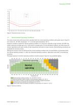
3.3 Recommended Operating Conditions The sensor shows best performance when operated within the normal operating conditions (dark green area in Figure 5). This means 20...80 %RH, temperature >0 °C and dew point temperature <60 °C. Exposure conditions outside this “Normal operating condition” for a long time, especially at high humidity >80 %RH may cause a temporary humidity gain error. If the sensor is brought back to normal operating conditions, the initial values will recover. Applications with high humidity at high temperatures will result in slower recovery. Reconditioning procedures can...
Open the catalog to page 8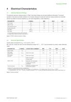
4.1 Absolute Maximum Ratings 1) Without I2C communication and when not measuring. 2) The chip temperature must not exceed 135°C with heater on. For example VDD = 3.3 V, heater current = 80 mA ^ Pheat = 0.264 W ^ Overtemperature ~40 °C (Rth ~ 150 K/W) ^ Ambient temperature < 95 °C ^ check the measured temperature while constant current heater is on. Table 6: General operation v1.7 / Modification rights reserved | 9
Open the catalog to page 9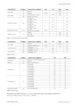
Table 9: General timing Subsequently, the typical time from VDD > VPORP to measurement ready in the standard configuration is: tRDY= tPWRU + tMEAS = tPWRU + tT + tRH + tCALC = 15.3 ms v1.7 / Modification rights reserved | 10
Open the catalog to page 10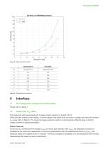
Table 10: Measurement resolution 5.1 Pin Configuration, Assignment and Description Please refer to chapter 1. The supply pins must be equipped with a bypass ceramic capacitor of at least 100 nF. When using the constant current heater, a current change in the heater must not lead to a voltage drop below the minimum VDD value (refer to Table 6). This means the bypass capacitor needs to be dimensioned sufficiently large so that the voltage controller is supplied adequately. Sensor Power-up As soon as VDD exceeds the POR voltage VPORP, the device gets initialized. After tPWRU, the initialization...
Open the catalog to page 11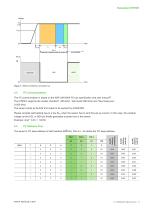
Datasheet HTE501 F:\proj\P\2016\P201607_EuE_ASIC_ASTRID1\04_DOC\Berechnungen\PWRup_HIpin_Modi Voltage VDD 3.3V VPORP tMEAS Automatic measurement at power-up IDLE MODE Figure 7: Sensor behaviour at power-up The I²C communication is based on the NXP UM10204 I²C bus specification and user manual1). The HTE501 supports the modes “standard“ (100 kHz), “fast mode“(400 kHz) and “fast mode plus” (1 000 kHz). The sensor works as SLAVE and needs to be queried by a MASTER. Please consider self-heating due to a low RPU when the sensor has to sink the pull-up current. In this case, the residual voltage on...
Open the catalog to page 12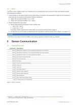
The HI pin means “Heater/Invalid” and it indicates that the measurement does not show the real environmental humidity and temperature conditions: 1. Internal heater on: the internal heater starts a self-heating, and therefore the temperature is higher and the humidity is lower than the surrounding environmental conditions actually are. b. Heater OFF (command 0x3066) ^ pin = high-Z 2. Recent measurement was invalid: a. Recent measurement (temperature or/and humidity) was: The status of each measurement (valid/invalid) can be read out from the status register 2. b. During power up until the start-up...
Open the catalog to page 13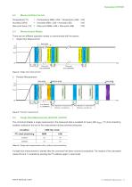
Measured Data Format Measurement Modes There are two different operation modes to communicate with the sensor: 1.shotSingle Single mode Shot Measurement G:\Produkte\HTEx01\501\Archive_Diagrams&Drawings\PWRup_HIpin_Modi Time depends on COMMAND Time depends on COMMAND READ Measurement READ Measurement time time IDLE MODE COMMAND COMMAND Break Break Measurement Measurement IDLE MODE tMEAS tMEAS tMEAS Time depends on measurement Time depends on measurement interval, 1 s at start‐up interval, 1 s at start‐up tMEAS tMEAS tMEAS Time depends on measurement Time depends on measurement interval, 1 s at...
Open the catalog to page 14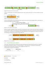
MEASUREMENT ONGOING tMEAS N P single shot 1 10: Start Figure 1 Without clock stretching MEASUREMENT FINISHED 16 BIT COMMAND measurement readout 16 BIT COMMAND Without clock stretching W FREE A A FOR OTHER CMD MSBBUS MEMBERS I2C-ADDRESS SCL S 0 0 0 SCL FREE FOR OTHER BUS MEMBERS A 4 3LSB 2 1 0 7 6 5 CMD W A A Figure Clock stretching during measurement CMD MSB I2C-ADDRESS S 11: CMD LSB MEASUREMENT ONGOING 0 0 0 16 BIT COMMAND MEASUREMENT FINISHED MEASUREMENT ONGOING tMEAS In case a command with clock stretching enabled has been issued, the slave holds SCL low until the calculation has been With...
Open the catalog to page 15All E+E ELEKTRONIK catalogs and technical brochures
 E+E Product Catalog 2026
19 Pages
 ISO9001 Calibration Services
7 Pages
 Datasheet Humor 20
8 Pages
 Datasheet TEE301
22 Pages
 Datasheet TEE501
25 Pages
 Datasheet EE461
8 Pages
 Datasheet EE462
7 Pages
 Datasheet EE451
10 Pages
 Datasheet EE471
10 Pages
 Datasheet EE431
11 Pages
 Datasheet EE074
8 Pages
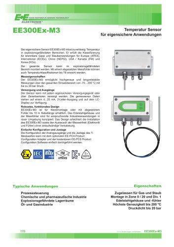 Datasheet EE300Ex-M3
5 Pages
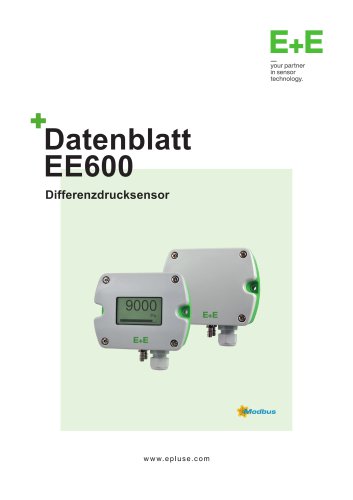 Datasheet EE600
9 Pages
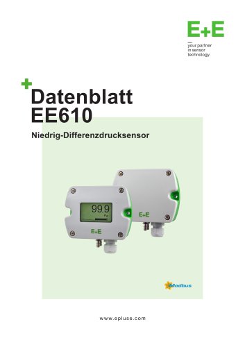 Datasheet EE610
9 Pages
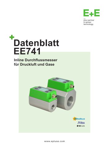 Datasheet EE741
13 Pages
 Datasheet EE771
13 Pages
 Datasheet EE772
13 Pages
 Datasheet EE776
13 Pages
 Datasheet EE671
8 Pages
 Datasheet EE650
9 Pages
 Datasheet EE576
7 Pages
 Datasheet EE660
10 Pages
 Datasheet EE680
10 Pages
 Datasheet EE895
7 Pages
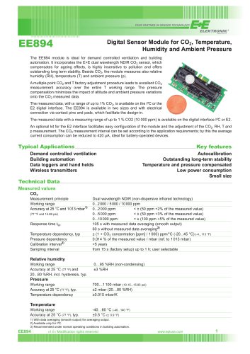 Datasheet EE894
3 Pages
 CDS201
9 Pages
 Datasheet EE850
9 Pages
 Datasheet EE820
7 Pages
 Datasheet EE8915
9 Pages
 Datasheet EE872
10 Pages
 Datasheet EE372
10 Pages
 Datasheet MOP301
10 Pages
 Datasheet EE364
9 Pages
 Datasheet EE381
9 Pages
 Datasheet EE360
12 Pages
 Datasheet EE354
9 Pages
 Datasheet EE355
9 Pages
 Datasheet EE371
10 Pages
 Datasheet HTE301
25 Pages
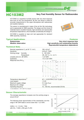 HC103M2
2 Pages
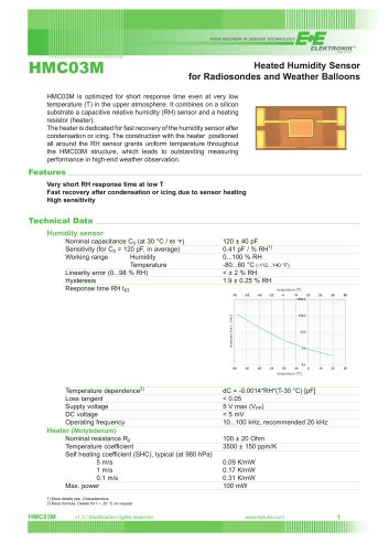 Datasheet HMC03M
2 Pages
 Datasheet EE03
6 Pages
 Datasheet EE046
8 Pages
 Datasheet EE040
7 Pages
 Datasheet HTS201
9 Pages
 Datasheet HTP201
10 Pages
 Datasheet EE160
9 Pages
 Datasheet EE072
10 Pages
 Datasheet EE08
9 Pages
 Datasheet EE99-1
7 Pages
 Datasheet EE100Ex
5 Pages
 Datasheet EE300Ex
7 Pages
 Datasheet TES201
8 Pages
 Datasheet HTS401
15 Pages
 AVS701 Datasheet
12 Pages
 Accessories
34 Pages
 Omniport 40 Datasheet
21 Pages
 Sigma05 Datasheet
8 Pages
 EE260 Datasheet
8 Pages
 EE220 Datasheet
10 Pages
 EE07 Datasheet
8 Pages
 EE212 Datasheet
11 Pages
 EE211 Datasheet
9 Pages
 EE210 Datasheet
13 Pages
 EE23 Datasheet
9 Pages
 EE310 Datasheet
10 Pages
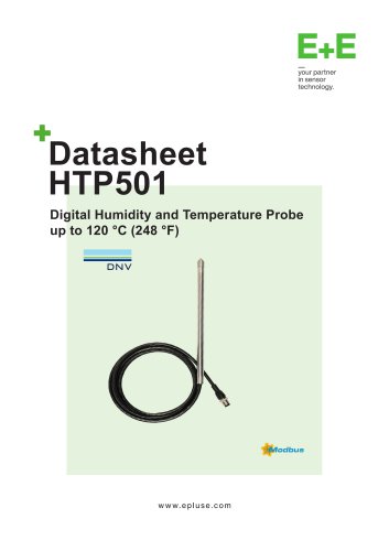 HTP501 Datasheet
9 Pages
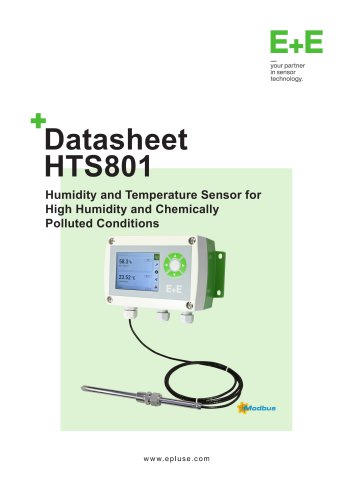 HTS801 Datasheet
12 Pages


- Flowmeter
- Volume flow monitor
- ERLO measuring instrument
- ERLO resistance temperature sensor
- ERLO calibrator
- Waterproof flow meter
- Gas flow monitor
- Industrial flow monitor
- ERLO pressure sensor
- Precision flow meter
- Waterproof temperature sensor
- In-line flow meter
- Pt100 temperature transducer
- DC flow monitor
- RS485 flow monitor
- Stainless steel temperature transducer
- Mass flow monitor
- Flow meter with display