- Catalogs
- E+E ELEKTRONIK
- Datasheet HTE301
Datasheet HTE301
1 /25Pages
Datasheet HTE301
1 /25Pages
Catalog excerpts

DatasheetHTE301 Digital Humidity and Temperature Sensor
Open the catalog to page 1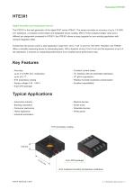
HTE301 Digital Humidity and Temperature Sensor The HTE301 is the next generation of the digital RH/T series HTEx01. The sensor provides an accuracy of up to 1.8 %RH incl. hysteresis, a constant current heater and integrated sensor coating. With a 16-bit unsigned integer value and a different pin assignment compared to HTE501, the HTE301 allows an easy upgrade for your existing application with minimal integration effort. Furthermore the sensor covers a wide application range from -40 to +125 °C and 0 to 100 %RH. Therefore, the HTE301 offers a versatile measuring device for demanding tasks. With...
Open the catalog to page 2
www.epluse.com v1.3 / Modification rights reserved | 3
Open the catalog to page 3
v1.3 / Modification rights reserved | 4
Open the catalog to page 4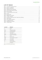
Table 1: List of HTE301 specific acronyms v1.3 / Modification rights reserved | 5
Open the catalog to page 5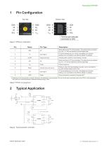
1 Pin Configuration Top view Bottom view Thermal pad internally connected to GND 1) Soldering of the thermal pad is optional. However, the soldering is recommended. Do not use the heat conduction pad on the PCB for heat dissipation but purely as a mounting surface, otherwise heating energy is lost. Figure 2: Typical application schematic v1.3 / Modification rights reserved | 6
Open the catalog to page 6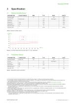
3 Specification 3.1 Relative Humidity Sensor Table 4: Temperature sensor parameters 1) In the periodic mode the humidity hysteresis is included. See also chapter 3.3 Recommended Operating Conditions. 2) In the periodic mode the humidity accuracy is within the hysteresis. In the single shot measurement, the humidity hysteresis must be added to the given humidity accuracy to obtain the overall accuracy. 3) The detailed definition of “typ.” and “max.” is given in the document Sensor Specification Accuracy, available at www.epluse.com/hte301. 4) Default resolution is 13 bit temperature / 13 bit humidity....
Open the catalog to page 7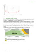
3.3 Recommended Operating Conditions The sensor shows best performance when operated within the normal operating conditions (dark green area in Figure 5). This means 20...80 %RH, temperature >0 °C and dew point temperature <60 °C. Exposure conditions outside this “Normal operating condition” for a long time, especially at high humidity >80 %RH may cause a temporary humidity gain error. If the sensor is brought back to normal operating conditions, the initial values will recover. Applications with high humidity at high temperatures will result in slower recovery. Reconditioning procedures can...
Open the catalog to page 8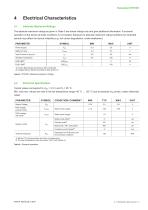
4.1 Absolute Maximum Ratings 1) Without I2C communication and when not measuring. 2) The chip temperature must not exceed 125°C with heater on. Table 6: General operation v1.3 / Modification rights reserved | 9
Open the catalog to page 9
Table 9: General timing Subsequently, the typical measurement time with high repeatability is: v1.3 / Modification rights reserved | 10
Open the catalog to page 10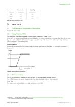
Table 10: Measurement resolution 5.1 Pin Configuration, Assignment and Description Please refer to chapter 1. The supply pins must be equipped with a bypass ceramic capacitor of at least 100 nF. When using the constant current heater, a current change in the heater must not lead to a voltage drop below the minimum VDD value (refer to Table 6). This means the bypass capacitor needs to be dimensioned sufficiently large so that the voltage controller is supplied adequately. Sensor Power-up As soon as VDD exceeds the POR voltage VPORP, the device gets initialized. After tPWRU, the initialization...
Open the catalog to page 11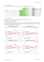
The sensor's I2C base address is 0x44 (without R/ bit). Pins A1...A2 define the I2C base address. The ALERT pin indicates low when the temperature and relative humidity are in the range: If any of temperature or relative humidity measurement values goes outside this range the ALERT pin will output high, which will remain high as long as the corresponding value will go back inside the given temperature or humidity range including the hysteresis as shown in the plots below. www.epluse.com v1.3 / Modification rights reserved | 12
Open the catalog to page 12
As soon as the falling edge on the reset pin is in the logic “0” blue area (low signal), as shown in the diagram below, the device goes into the reset and remains in this state as along as the voltage on the reset pin remains in the logic “0” area. In particular, during this phase, the device is in the cycle of being powered-up and reset immediately after power-up, thus the current consumption corresponds to the power-up current, approximately 1 mA. During the reset time, the device will not respond to any request on the I2C interface and set all digital outputs into a tristate mode. As soon...
Open the catalog to page 13
6 Sensor Communication 6.1 Command Overview 6.2 Measured Data Format v1.3 / Modification rights reserved | 14
Open the catalog to page 14
Measurement Modes There are two different operation modes to communicate with the sensor: 1.shotSingle Single mode Shot Measurement G:\Produkte\HTEx01\501\Archive_Diagrams&Drawings\PWRup_HIpin_Modi tPWRU tMEAS Time depends on COMMAND Time depends on COMMAND time time tMEAS IDLE MODE IDLE MODE COMMAND COMMAND Break Break Measurement Measurement Measurement Measurement COMMAND COMMAND Fetch Measurement Fetch Measurement Measurement Measurement COMMAND COMMAND Periodic Mode Periodic Mode Single Measurement Single Measurement at powerat uppower up optional COMMAND optional COMMAND Fetch Measurement...
Open the catalog to page 15
MEASUREMENT ONGOING tMEAS N P single shot 1 10: Start Figure 1 Without clock stretching MEASUREMENT FINISHED 16 BIT COMMAND measurement readout 16 BIT COMMAND Without clock stretching W FREE A A FOR OTHER CMD MSBBUS MEMBERS I2C-ADDRESS SCL S 0 0 0 SCL FREE FOR OTHER BUS MEMBERS A 4 3LSB 2 1 0 7 6 5 CMD W A A Figure Clock stretching during measurement CMD MSB I2C-ADDRESS S 11: CMD LSB MEASUREMENT ONGOING 0 0 0 16 BIT COMMAND MEASUREMENT FINISHED MEASUREMENT ONGOING tMEAS In case a command with clock stretching enabled has been issued, the slave holds SCL low until the calculation has been With...
Open the catalog to page 16
Figure 14: Periodic measurement commands A periodic measurement command with a different measurement interval / resolution can be issued at any time, but the calculated value will be updated according the new settings earliest after a measurement with the new settings has been performed. Readout of calculation results in periodic measurement mode can be performed using the fetch command. This is similar to the readout of measurement results in single-shot mode, except that clock stretching is always disabled. The slave will answer with NACK if no measurement results are available. www.epluse.com...
Open the catalog to page 17All E+E ELEKTRONIK catalogs and technical brochures
 E+E Product Catalog 2026
19 Pages
 ISO9001 Calibration Services
7 Pages
 Datasheet Humor 20
8 Pages
 Datasheet TEE301
22 Pages
 Datasheet TEE501
25 Pages
 Datasheet EE461
8 Pages
 Datasheet EE462
7 Pages
 Datasheet EE451
10 Pages
 Datasheet EE471
10 Pages
 Datasheet EE431
11 Pages
 Datasheet EE074
8 Pages
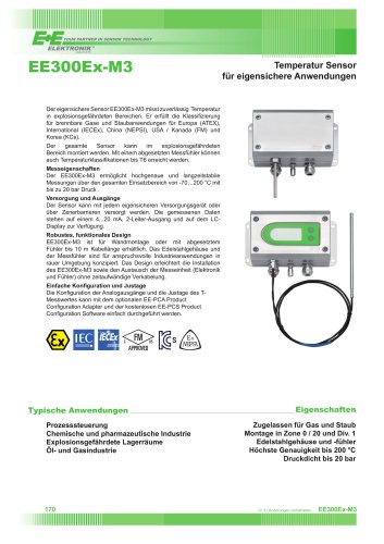 Datasheet EE300Ex-M3
5 Pages
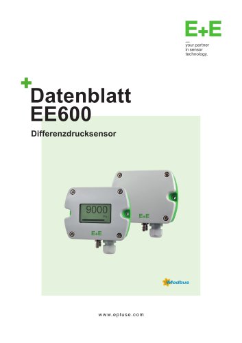 Datasheet EE600
9 Pages
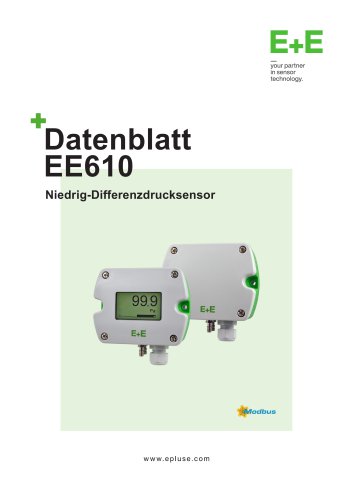 Datasheet EE610
9 Pages
 Datasheet EE741
13 Pages
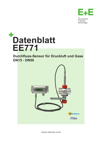 Datasheet EE771
13 Pages
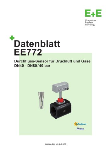 Datasheet EE772
13 Pages
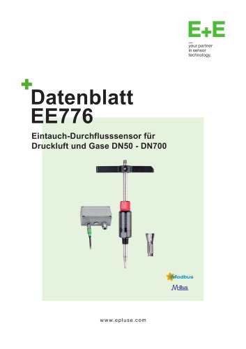 Datasheet EE776
13 Pages
 Datasheet EE671
8 Pages
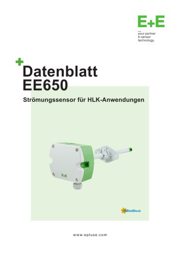 Datasheet EE650
9 Pages
 Datasheet EE576
7 Pages
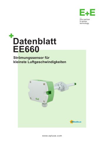 Datasheet EE660
10 Pages
 Datasheet EE680
10 Pages
 Datasheet EE895
7 Pages
 Datasheet EE894
3 Pages
 CDS201
9 Pages
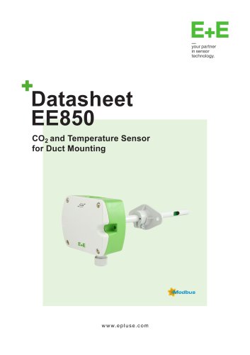 Datasheet EE850
9 Pages
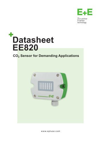 Datasheet EE820
7 Pages
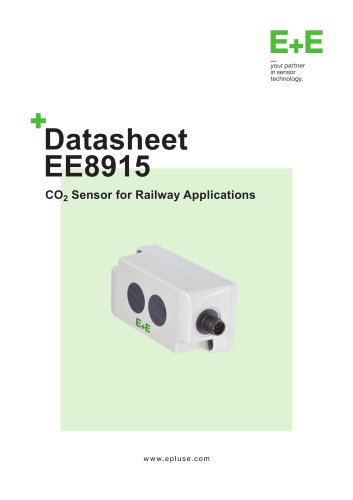 Datasheet EE8915
9 Pages
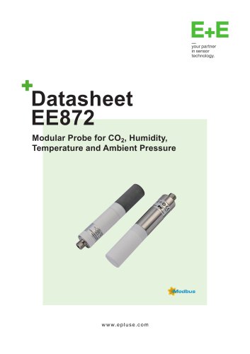 Datasheet EE872
10 Pages
 Datasheet EE372
10 Pages
 Datasheet MOP301
10 Pages
 Datasheet EE364
9 Pages
 Datasheet EE381
9 Pages
 Datasheet EE360
12 Pages
 Datasheet EE354
9 Pages
 Datasheet EE355
9 Pages
 Datasheet EE371
10 Pages
 Datasheet HTE501
27 Pages
 HC103M2
2 Pages
 Datasheet HMC03M
2 Pages
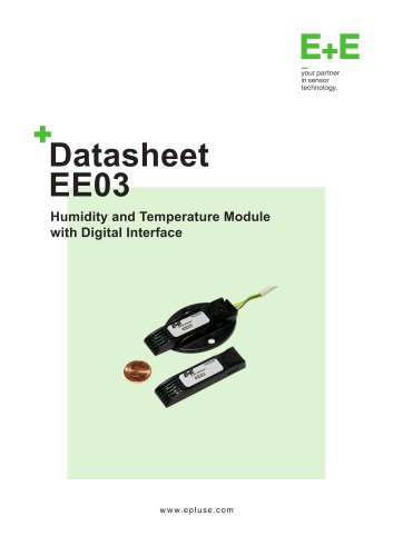 Datasheet EE03
6 Pages
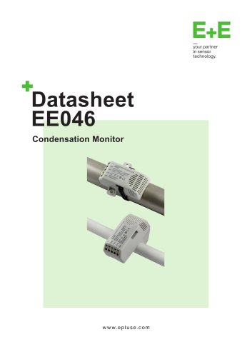 Datasheet EE046
8 Pages
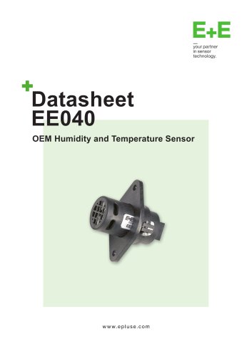 Datasheet EE040
7 Pages
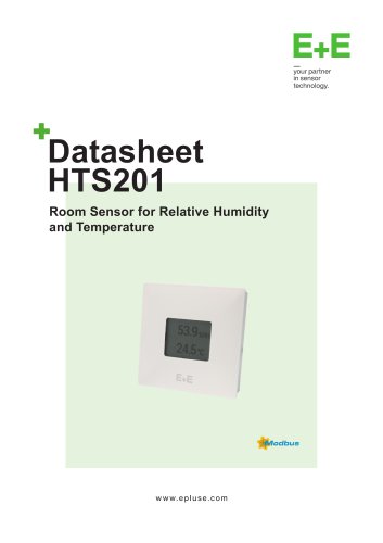 Datasheet HTS201
9 Pages
 Datasheet HTP201
10 Pages
 Datasheet EE160
9 Pages
 Datasheet EE072
10 Pages
 Datasheet EE08
9 Pages
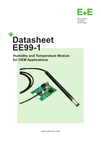 Datasheet EE99-1
7 Pages
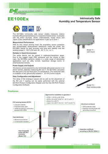 Datasheet EE100Ex
5 Pages
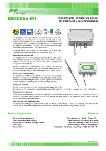 Datasheet EE300Ex
7 Pages
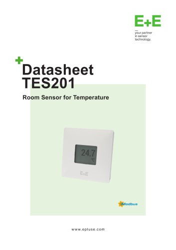 Datasheet TES201
8 Pages
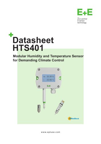 Datasheet HTS401
15 Pages
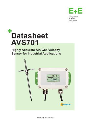 AVS701 Datasheet
12 Pages
 Accessories
34 Pages
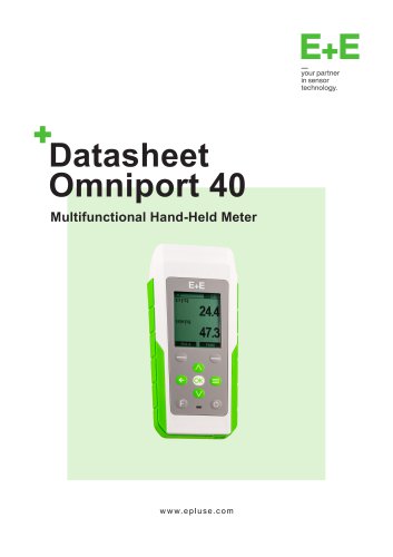 Omniport 40 Datasheet
21 Pages
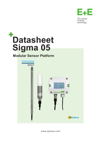 Sigma05 Datasheet
8 Pages
 EE260 Datasheet
8 Pages
 EE220 Datasheet
10 Pages
 EE07 Datasheet
8 Pages
 EE212 Datasheet
11 Pages
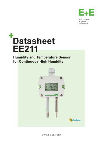 EE211 Datasheet
9 Pages
 EE210 Datasheet
13 Pages
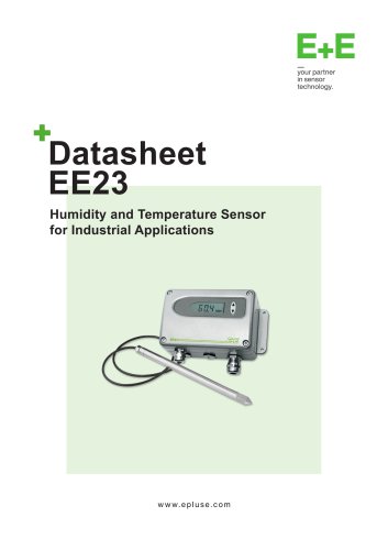 EE23 Datasheet
9 Pages
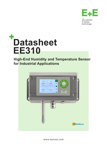 EE310 Datasheet
10 Pages
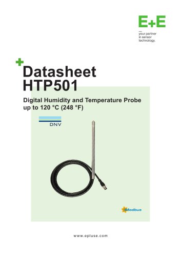 HTP501 Datasheet
9 Pages
 HTS801 Datasheet
12 Pages


- ERLO flow meter
- ERLO volume flow meter
- ERLO measuring instrument
- ERLO resistance temperature sensor
- ERLO calibrator
- ERLO waterproof flow meter
- ERLO gas flow meter
- ERLO industrial flow meter
- ERLO pressure sensor
- ERLO precision flow meter
- ERLO waterproof temperature sensor
- In-line flow meter
- Pt100 temperature transducer
- ERLO DC flow meter
- ERLO RS485 flow meter
- ERLO humidity and temperature sensor
- Stainless steel temperature transducer
- Mass flow monitor
- ERLO flow meter with display