- Catalogs
- Dynatect Manufacturing, Inc.
- NYLATRAC ® MODULAR TS series
NYLATRAC ® MODULAR TS series
1 /2Pages

NYLATRAC ® MODULAR TS series
1 /2Pages
Catalog excerpts
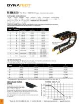
TS SERIES | NYLATRAC® MODULAR (open- & enclosed-style carriers) PART NUMBER CONFIGURATION: Model TS Following above example, add dashes. Part number = TS-MB-9.79-245-0-101.50-#2IN-#2IN Bar width is specified in inches, to two decimals. Separators per link specified; use ‘0’ for none. Carrier Length (between flanges) is specified to two decimals in inches. Total number of links depends on pitch length. Specify arrangement # and mounting hole direction (IN or OUT) each bracket. SPECIFICATIONS MODEL Shown with optional modular sliders. Customer Specified Customer Specified Customer Specified TS-RB = 2.45 (3.65) TS-PR = 2.69 (4.00) TS-AF = 4.93 (7.34) TS-AFS = 4.81 (7.16) TS-PL = 4.33 (6.44) TS-AP = 6.39 (9.51) *Bar Styles (Top and Bottom): MB = Snap-In Plastic Flat Bar RB = Bolted Aluminum Round Bar PR = Poly Roller over Bolted Aluminum Round Bar AF = Bolted Aluminum Flat Bar AFS = Snap-In Aluminum Flat Bar PL = Plastic Lid (Enclosed-Style Carrier) AP = Aluminum Armor Plate (Enclosed-Style Carrier) 360 16.13 (410) 35.50 (902) 21.81 (554) ***The following options are not available with 110 and 140 curve heights: modular sliders, aluminum armor plates, plastic lids. MODULAR LOW-FRICTION SLIDERS When adding sliders to TS Series, add 0.20” (5 mm) to overall track width (‘C’ dimension). ADDITIONAL LOAD – LBS/FT (kg/m) TS SERIES – WEIGHT LOAD Modular sliders are often used in long travel applications in which chain bands glide on each other. Sliders are manufactured from special plastic material that is wear-resistant and provides a low coefficient of friction. Not only do they reduce tow force and wear, but they are removable and easy to replace.
Open the catalog to page 1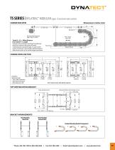
TS SERIES | NYLATRAC® MODULAR (open- & enclosed-style carriers) Dimensions in inches (mm) CARRIER SIDE VIEW 1/2 Total Travel Total Travel 1/2 Total Travel Moving End Recommended Clearance Above Track 2.50 (64) Travel/2 + CL (+ Offset Distance From Center*) = Length Dynatect recommends mounting the stationary end of the carrier at the center of travel, minimizing the required length. In cases where center mounting is not possible, add the distance offset from center to the carrier length calculation. Support Surface CARRIER CROSS SECTION C A MB = 2.19 (56) Dynatect Recommends: • 10% Cable Clearance...
Open the catalog to page 2All Dynatect Manufacturing, Inc. catalogs and technical brochures
 Gortube®
4 Pages
 GORTRAC ® STEEL SA series
2 Pages
 Bellows Brochure
28 Pages
 Ball Screw
6 Pages
 Precision Slip Clutch Full
22 Pages
 Dynatect Cable & Hose Carriers
99 Pages