
- Catalogs
- DYNABRADE Europe
- DYNABRADE AIR TOOL


DYNABRADE AIR TOOL

DYNABRADE AIR TOOL
This section underscores the necessity of understanding safety symbols and guidelines before using pneumatic tools. It highlights the use of safety signal words like 'Danger', 'Warning', and 'Notice' to denote different hazard levels. Compliance with industry safety standards such as OSHA and ANSI is mandatory.
The document details the components of a compressed air supply system, including air intake filters, compressors, air cooling/drying systems, air storage tanks, and distribution systems. It emphasizes maintaining clean, lubricated air to protect air tools.
Guidance is provided on selecting the appropriate compressor based on PSIG needs, air consumption, and horsepower requirements. The document explains the importance of SCFM and the necessity for adequate air storage tank size and control systems.
This section discusses the importance of using the correct air supply hose diameter and length to prevent air flow restrictions, providing a chart for recommended hose sizes based on SCFM requirements.
The guide advises against using air plugs and couplers due to contamination risks, suggesting direct thread connections to minimize debris entering the air motor.
Recommendations include reducing condensation in the air supply, filtering air to prevent debris, and maintaining clean air inlet connections. The use of water traps, after-coolers, and refrigerated air dryers is advised to ensure a good air supply.
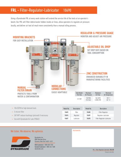
Details on air tool lubricants, Dynaswivel®, and DynaJet in-line blow guns are provided. The importance of using filter-regulator-lubricator systems is emphasized to maintain tool performance.
This section ensures that tools are maintained to perform optimally, with references to special and general repair tools.
Includes a measurement conversion table and contact information for further assistance.
To ensure optimal performance and longevity of air motors, it is crucial to prevent dust from entering the motor and avoid using compressed air for cleaning, as it may force debris into the bearings. Regular lubrication is essential, either through an automatic lubricator or manually by applying 2-3 drops of air motor oil at various times throughout the day.
Maintaining clear airflow is vital. Ensure the tool's air inlet is free from debris and clean or replace exhaust muffler elements as needed.
Use the manufacturer's specified lubricant for gears, sleeves, bearings, and sliders, applying the recommended amount at specified intervals.
Adhere to the specified maximum operating air pressure and RPM for all tools and accessories to prevent damage and ensure safety.
Dynabrade offers various lubricants and accessories, such as the Dynabrade Air Lube, which absorbs water and prevents rust, and the Dynaswivel®, which enhances tool maneuverability and reduces operator fatigue.
Installing a drop-in motor requires following specific disassembly and assembly instructions, using special repair tools, and ensuring proper alignment and lubrication. Allow adhesives to cure for 30 minutes before operation.
Dynabrade provides a comprehensive list of special repair tools, including repair collars, lock ring wrenches, bearing removal tools, and more, to assist in the maintenance and repair of air tools.
Regular checks of the air system, including the condition of the air tool, air inlet, spindle, exhaust, and air supply pressure, are necessary to ensure proper functioning and prevent issues such as broken vanes due to inadequate lubrication.
The document outlines the importance of inspecting air hoses for frays or cracks and matching the hose length and internal diameter (I.D.) to the air requirements of the tool. It also suggests checking for hose reels and the number of coupler connections from the drop to the workbench. The use of Dynaswivel® is recommended to prolong hose life.
The presence and functionality of the FRL system are crucial. It should be filled with the correct type of oil, and the document distinguishes between non-detergent and detergent oils. The connection of the air supply to the FRL should be checked for reducer bushings, and the material of the pipe carrying the air supply should be identified.
The document provides guidelines for inspecting air tools, specifically focusing on sanding techniques. It recommends a specific sanding pattern and emphasizes the importance of inspecting abrasives for defects. The air motor SCFM and recommended hose and fitting I.D. are provided for different airflows.
The required operating air supply pressure is 90 PSIG (6.2 Bar). The document advises checking the tool's free speed RPM and inspecting the balancer bearing and back-up pad for defects.
A detailed analysis of the cost implications of a leaking air hose is provided, highlighting the significant air loss and associated costs.
Contact details for various organizations, including ANSI, CAGI, and CEN, are provided, along with measurement conversion formulas from US to international units.
Catalog excerpts

DYNABRADE AIR TOOL MAINTENANCE GUIDE
Open the catalog to page 1
CAREFULLY READ ALL INSTRUCTIONS BEFORE OPERATING, MAINTAINING OR SERVICING ANY POWER TOOL CONTACT YOUR DYNABRADE REPRESENTATIVE FOR PRICING OF PRODUCTS SHOWN IN THIS GUIDE
Open the catalog to page 2
For Various Abrasive Power Tools Safety Booklet included with tool must be read and understood before operating any portable pneumatic tool! • This page must be read and understood by operating personnel and safety manager. Protection to operating personnel, as well as adjacent areas, shall be maintained at all times. • Always comply with: General Industry Safety & Health Regulations (www.osha.gov), EN Standards for Hand Held Non-Electric Power Tools (www.cen.eu), American National Standards Institute (www.ansi.org) and Regional Regulations. • Additional safety reference materials are available...
Open the catalog to page 3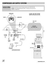
COMPRESSED AIR SUPPLY SYSTEM Lubricator Setting 1 Drop /Minute per 20 SCFM Dynabrade recommends one drop of air lube per minute for each 20 SCFM (566 L/Min) Example: If the tool specifications state 40 SCFM (1,133 L/Min), set the drip rate of your lubricator at 2 drops per min. CLOSED LOOP PIPE SYSTEM (SLOPED IN THE DIRECTION OF AIR FLOW) REGULATOR FILTER TO TOOL STATION 6 BALL VALVE DRAIN VALVE DRAIN VALVE COUPLER BALL VALVE
Open the catalog to page 4
COMPRESSED AIR SUPPLY SYSTEM (CONT.) COMPRESSED AIR SUPPLY SYSTEM (CONT.) COMPRESSED AIR SYSTEMS SHOULD INCLUDE THE FOLLOWING: 1. AIR INTAKE FILTER Incoming air must be filtered to remove dust and other contaminants. 2. AIR COMPRESSOR The filtered air is compressed using; a screw, or reciprocating compressor. 3. AIR COOLING/DRYING Air usually contains a significant amount of water vapor. As air is compressed its temperature is dramatically raised, so cooling of the compressed air is required. As the air is cooled, the water vapor condenses and water is removed. 4. AIR STORAGE A tank called an...
Open the catalog to page 5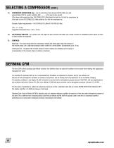
SELECTING A COMPRESSOR (CONT.) C) COMPRESSOR HORSEPOWER (hp) – Use the determined total demand SCFM (L/Min) and add approximately 20% for system variables. Add ______% for (your) future growth. If the above total equals less than 100 SCFM(2,832 L/Min) divide this total by 4 to find the compressor hp. If the total is over 100 SCFM(2,832 L/Min) divide by 5 to find the compressor hp. Example: System requirements = 165 SCFM (4,673 L/Min) @ 100 PSIG (6.9 Bar) 165 ÷ 5 = 33 hp. Suggested Compressor Size: ~30 to ~40 hp. AIR STORAGE TANK SIZE - As a general rule, the larger the tank (receiver) the better....
Open the catalog to page 6
PREVENT AND ELIMINATE AIR SUPPLY RESTRICTIONS Common causes of restriction: • The air supply hose is too long. • The inside diameter (i.d.) of the hose is too small. • The air connections or fittings have an inside diameter that is too small. • There are too many air connections or fittings being used. • If an inline filter is being used, the unit may be too small or the filter element may be plugged. • If an inline regulator is being used, the unit may be to small, not adjusted properly or defective. • The air supply hose, air fitting, air tool inlet or air tool exhaust may be plugged....
Open the catalog to page 7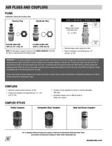
AIR PLUGS AND COUPLERS PLUGS COMPARE AIRFLOW SCFM(LPM) Common Plug HOW TO MEASURE A TYPICAL PLUG Dynabrade Plug NPT (National Pipe Thread) is the thread size. (i.e. 1/4" NPT) Thread Size • Dynbrade plugs provide maximum air flow NOTE: All information is based on the size of the INSIDE DIAMETER @ 90 PSIG (6.2 Bar) in conjunction with the mating coupler. • Plugs are available in the following sizes: 1/4", 3/8"and 1/2" NPT. IMPORTANT: It is not always advisable to use an air plug and coupler to connect an air tool to the air supply hose. Contaminants can enter the air tool through plug and coupler...
Open the catalog to page 8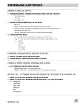
1. REDUCE OR ELIMINATE CONDENSATION (WATER VAPOR) FROM THE AIR SUPPLY • Water traps and drains • After-coolers • Refrigerated air dryer 2. PREVENT DEBRIS FROM ENTERING THE AIR MOTOR • Filter the air. • Keep the air inlet connections, plugs and couplers clean, free of dust and debris. • Keep exhaust mufflers and elements in place. Muffler elements provide a barrier that will prevent dust from being pulled into the air motor. • Do not use compressed air to blow-off the tool, this could force debris into bearings. 3. LUBRICATE THE AIR MOTOR • Use an automatic lubricator to supply the correct weight...
Open the catalog to page 9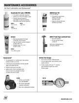
95848 Gear Oil 2.5 oz. (74 ml) tube • Formulated for geared tools utilizing a wick-type lubrication system. • Failure to lubricate will cause premature gear failure. Dynabrade Air Lube (10W/NR) • Formulated for pneumatic equipment. • Absorbs up to 10% of its weight in water. • Prevents rust and formation of gum/sludge for longer tool operation with greater power and less downtime. 95821 95843 Grease • Multi-purpose grease for all types of bearings, cams and gears. • High film strength; excellent resistance to water, steam, etc. • Workable range: 0°F (-17°C) to 300°F (148°C). 95542 10 oz. (283.5...
Open the catalog to page 10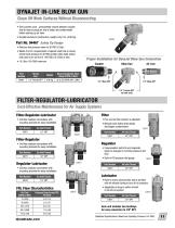
• Only connect once... permanently mounts between coupler and air hose to purge air line of water and contaminants before starting up air tools. • Durable aluminum construction, weighs only 2 oz. (0.06 kg). Part No. 94467 Safety Tip Design • Reduces line pressure down to 30 PSIG (2 Bar). • Meets O.S.H.A. requirements of special relief hole in nozzle, which limits pressure to 30 PSIG (2 Bar) when dead-ended and used on an air line of 150 PSIG (10.3 Bar) or less. • 10.3 Bar (150 PSIG) maximum Proper Installation for DynaJet Blow Gun Connection Part Number FILTER-REGULATOR-LUBRICATORCost-Effective...
Open the catalog to page 11
DROP-IN MOTORS/TUNE-UP KITS • Drop-In Motors are complete replacement air motor assemblies. • Tune-Up Kits contain assorted and high wear replacement parts. To view a complete offering, go to Dynabrade.com Drop-In Motor GUIDELINES FOR INSTALLING A DROP-IN MOTOR Installing a Drop-In Motor is relatively simple to perform. However, there are some necessary steps to follow to be successful. 1) Before attempting the installation of a drop-in-motor, review and understand the specific power tool “Disassembly and Assembly Instructions”. Note: Though a technician is not disassembling every component,...
Open the catalog to page 12All DYNABRADE Europe catalogs and technical brochures
 Dynabrade Abrasive System Products
100 Pages
 TOOLS FOR THE AEROSPACE
16 Pages
 Dynabrade Clean Air Solution
116 Pages
 Dynabrade Backing Pads
8 Pages
 Dynabrade Metalworking D20-10
32 Pages
 MINI-RAPTOR VAC PACKS
6 Pages
 SANDING SOLUTIONS
6 Pages
 Steel Housing Die Grinders
4 Pages
 dybabrade air tool
20 Pages
 Performance Assurance
2 Pages
 Mini Raptor Vac Packs
6 Pages
 Tools for Aerospace Industries
20 Pages
 51520
515202 Pages
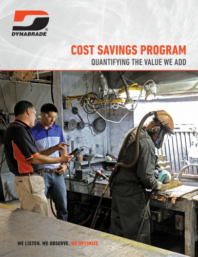 COST SAVINGS PROGRAM
4 Pages
 RAPTOR VAC CART
4 Pages
 600 SERIES
2 Pages
 300 SERIES
2 Pages
 DYNACUT EXTREME ORANGE
2 Pages
 DYNORBITAL EXTREME
6 Pages
 DYNISHER
4 Pages
 DYNAPOINT II
2 Pages
 Downdraft Sanding Tables
2 Pages
 Dynabrade Abrasive Power Tools
96 Pages
 Steel Housing Die Grinders
4 Pages
 Wrenchless Pencil Grinder
2 Pages
 Quick-Change Pencil Grinder
2 Pages
 DynaPen Series
4 Pages
 Pencil Filer from Dynabrade
2 Pages
 Industrial Quality Drills
12 Pages
 Tools for the Wind Energy
16 Pages
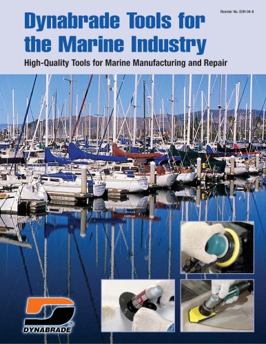 Tools for the Marine Industry
32 Pages
 Vacuum Tools & Accessories
64 Pages


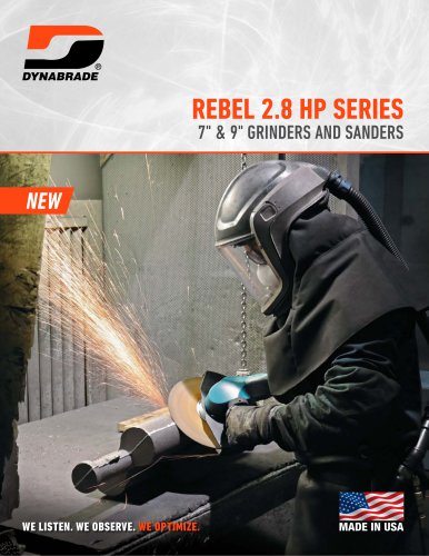




- Industrial press
- Milling tool
- Forming press
- Metal sawing line
- Grinding machine
- Milling tool with replaceable insert
- Surface treatment brush
- Portable grinder
- Drill
- Corner radius milling cutter
- Manual press
- Surface grinding machine
- Cylindrical grinding machine
- Plastic saw
- Sanding disc
- Electric sander
- Metal brush
- Air-operated portable grinder
- Circular brush