- Catalogs
- Duplomatic Oleodinamica
- IGP INTERNAL GEAR PUMPS
IGP INTERNAL GEAR PUMPS
1 /20Pages

IGP INTERNAL GEAR PUMPS
1 /20Pages
Catalog excerpts
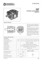
INTERNAL GEAR PUMPS OPERATING PRINCIPLE — IGP pumps are volumetric displacement pumps with internal gears, available in five sizes, each divided into a range of different displacement. — The pumps feature high volumetric performance levels, thanks to both radial and axial compensation in proportion to operating pressure, in addition to low noise levels. — Optimal load distribution and special friction bearings enable continuous duty at high pressures and ensure extended pump lifetime. — IGP pumps are also available in multiple versions which can be combined to make multi-flow groups. TECHNICAL SPECIFICATIONS Displacement range Flow rate range (at 1.500 rpm) Operating pressures Rotation speed Rotation direction clockwise or anticlockwise (seen from the shaft side) consult our technical department for the extent of axial and radial loads Hydraulic connection flanged fittings SAE J518 c code 61 (see par. 28) Mass (single pump) Ambient temperature range Fluid temperature range Degree of fluid contamination 12 100/110 ED HYDRAULIC SYMBOL Fluid viscosity range Recommended true viscosity
Open the catalog to page 1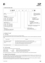
SERIES 10 1 - IDENTIFICATION CODE / 10 Series No. (the overall and mounting dimensions remain unchanged from 10 to 19) Internal gear pump Pump size: - single pump - front pump (only for double pumps): 3 4 5 6 7 from from from from from Type of shaft end 1 = with key other types of shafts are available upon request Mounting flange 0 =type SAE - 2 1 =type SAE - 4 (only for IGP7) other flange types are available upon request Added pump size (only for double pumps): 3 4 5 6 7 from from from from from Rotation direction (seen from the shaft side) R = clockwise L = anticlockwise Added pump size: (only...
Open the catalog to page 2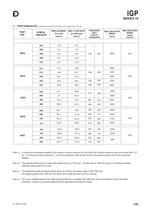
SERIES 10 3 - PERFORMANCES PUMP SIZE (obtained with mineral oil with viscosity in the range of 25 ÷ 100 cSt) NOMINAL DIMENSION DISPLACEMENT MAX. FLOW RATE (at 1500 rpm) [cm3/rev] [l/min.] (note 2) PRESSURE [bar] (note 3) steady/peak MIN. ROTATION SPEED [rpm] (note 4) In continuous operating conditions, the maximum suction pressure is 2 bar while the minimum pressure must not be less than -0,2 bar. A minimum suction pressure of - 0,4 bar is allowed for brief periods of time (the pressure values are to be considered relative). The working tolerances can reduce the displacement by 1,5% max. The...
Open the catalog to page 3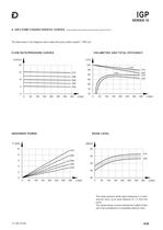
4- IGP3 PUMP CHARACTERISTIC CURVES (values obtained with mineral oil with viscosity of 46 cSt at 40DC) The data shown in the diagrams were noted with pump rotation speed = 1500 rpm. FLOW RATE/PRESSURE CURVES VOLUMETRIC AND TOTAL EFFICIENCY ABSORBED POWER NOISE LEVEL The noise pressure levels were measured in a semi- anecoic room, at an axial distance of 1 m from the The values shown must be reduced by 5 dB(A) if they are to be considered in a completely anecoic room.
Open the catalog to page 4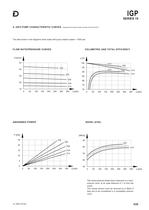
5- IGP4 PUMP CHARACTERISTIC CURVES (obtained with mineral oil with viscosity of 46 cSt at 40DC) The data shown in the diagrams were noted with pump rotation speed = 1500 rpm. FLOW RATE/PRESSURE CURVES VOLUMETRIC AND TOTAL EFFICIENCY ABSORBED POWER NOISE LEVEL The noise pressure levels were measured in a semi- anecoic room, at an axial distance of 1 m from the The values shown must be reduced by 5 dB(A) if they are to be considered in a completely anecoic
Open the catalog to page 5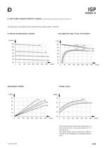
6- IGP5 PUMP CHARACTERISTIC CURVES (values obtained with mineral oil with viscosity of 46 cSt at 40DC) The data shown in the diagrams were noted with pump rotation speed = 1500 rpm. FLOW RATE/PRESSURE CURVES VOLUMETRIC AND TOTAL EFFICIENCY ABSORBED POWER NOISE LEVEL The noise pressure levels were measured in a semi-anecoic room, at an axial distance of 1 m The values shown must be reduced by 5 dB(A) if they are to be considered in a completely anecoic
Open the catalog to page 6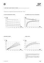
7- IGP6 PUMP CHARACTERISTIC CURVES (obtained with mineral oil with viscosity of46 cSt at 40°C) The data shown in the diagrams were noted with pump rotation speed = 1500 rpm. FLOW RATE/PRESSURE CURVES VOLUMETRIC AND TOTAL EFFICIENCIES ABSORBED POWER NOISE LEVEL The noise pressure levels were measured in a semi-anecoic room, at an axial distance of 1 m from The values shown must be reduced by 5 dB(A) if they are to be considered in a completely anecoic
Open the catalog to page 7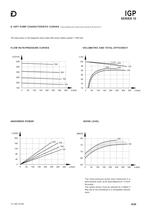
8- IGP7 PUMP CHARACTERISTIC CURVES (values obtained with mineral oil with viscosity of 46 cSt at 40°C) The data shown in the diagrams were noted with pump rotation speed = 1500 rpm. FLOW RATE/PRESSURE CURVES VOLUMETRIC AND TOTAL EFFICIENCY ABSORBED POWER NOISE LEVEL The noise pressure levels were measured in a semi-anecoic room, at an axial distance of 1 m from The values shown must be reduced by 5 dB(A) if they are to be considered in a completely anecoic
Open the catalog to page 8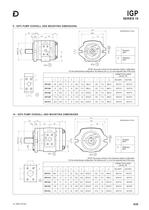
SERIES 10 9 - IGP3 PUMP OVERALL AND MOUNTING DIMENSIONS dimensions in mm Suction port Delivery port NOTE: the pump is shown in the clockwise rotation configuration For the anticlockwise configuration, the delivery port, 2), is on the opposite side of the pump CONNECTION FLANGE (see par. 28) c 10 - IGP4 PUMP OVERALL AND MOUNTING DIMENSIONS dimensions in mm Suction port Delivery port NOTE: the pump is shown in the clockwise rotation configuration For the anticlockwise configuration, the delivery port, 2), is on the opposite side of the pump CONNECTION FLANGE (see par. 28) c
Open the catalog to page 9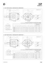
SERIES 10 11- IGP5 PUMP OVERALL AND MOUNTING DIMENSIONS dimensions in mm Suction port Delivery port NOTE: the pump is represented in the clockwise rotation configuration For the anticlockwise configuration, the delivery port, 2), is on the opposite side of the pump CONNECTION FLANGES (see par. 28) c 12- IGP6 PUMP OVERALL AND MOUNTING DIMENSIONS dimensions in mm Suction port Delivery port NOTE: the pump is represented in the clockwise rotation configuration For the anticlockwise configuration, the delivery port, 2), is on the opposite side of the pump CONNECTION FLANGES (see par. 28) c
Open the catalog to page 10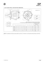
SERIES 10 13- IGP7 PUMP OVERALL AND MOUNTING DIMENSIONS Suction port Delivery port NOTE: the pump is shown in the clockwise rotation configuration For the anticlockwise configuration, the delivery port, 2), is on the opposite side of the pump CONNECTION FLANGES (see par. 28) c NOTE 5: For applications with delivery pressure greater than 200 bar, it is necessary to use the special connection flange, code 0610725.
Open the catalog to page 11All Duplomatic Oleodinamica catalogs and technical brochures
 Energy eng
4 Pages
 Full catalogue
1289 Pages
 PZM2
PZM22 Pages
 1P EXTERNAL GEAR PUMPS
4 Pages
 GP - External gear pumps
16 Pages
 Mobile eng
3 Pages
 Industrial eng
5 Pages
 Machine tool eng
6 Pages
 Metal forming eng
6 Pages
 Mobile eng
2 Pages
 Leaflet Axes Control System
2 Pages
- ERLO valve
- ERLO manual valve
- ERLO control valve
- ERLO ball valve
- Cylinder
- ERLO solenoid valve
- Regulating valve
- Flap valve
- Check valve
- ERLO 2-way solenoid valve
- Directional control valve
- Double-acting cylinder
- Hydraulic pump
- Hydraulic cylinder
- Oil valve
- Hydraulic valve
- 2-channel valve
- ERLO signal amplifier
- Electrically-actuated valve
- Hydraulic directional control valve