- Catalogs
- Duplomatic Oleodinamica
- GP - External gear pumps
GP - External gear pumps
1 /16Pages

GP - External gear pumps
1 /16Pages
Catalog excerpts
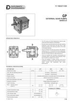
EXTERNAL GEAR PUMPS SERIES 20 OPERATING PRINCIPLE — The GP pumps are fixed displacement external gear pumps with axial clearance compensation. — They give high volumetric flows even with high operating pressures, a low noise level, and they have a high endurance thanks to the balancing system of the loads on the guide bushings. — They are divided into three size groups, with displacements of up to 9,1 - 27,9 and 87,6 cm3/rev respectively, and with operating pressures of up to 250 bar (standard) and up to 310 bar (version for high pressures H). — They are available with clockwise, anticlockwise and reversible rotation, with tapered shaft (standard). Other kind of shaft are available upon request. — They are available in multiple versions, and can be combined in multi-flow groups, with a splined connection motion system that guarantees high power performances. TECHNICAL SPECIFICATIONS GP PUMP SIZE Displacement range Flow rate and operating pressures Rotation speed Rotation direction clockwise, anticlockwise or reversible (seen from the shaft side) radial and axial load are not allowed Max torque applicable to the shaft Hydraulic connection flanged fittings (see paragraph 16) 4 hole flange - rectangular type Mass: standard version version H Ambient temperature range Fluid temperature range HYDRAULIC SYMBOL Fluid viscosity range Fluid contamination degree Recommended viscosity 11 100/211 ED
Open the catalog to page 1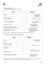
SERIES 20 1 - IDENTIFICATION CODE 1.1 - Identification code for single and front pumps External gear pump H = version for high pressures (omit for standard pressure) (not available for reversible pumps) Seals: N = NBR seals for mineral oils omit for single pumps (standard) F = only for front pump to be coupled Series No. (from 20 to 29 sizes and mounting dimensions remain unchanged) Nominal size (see table 3 - Performances) Hydraulic connection F = flanged ports (standard) B = BSP threaded ports U = UNF threaded ports Rotation direction (seen from the shaft side) R = clockwise (standard) L =...
Open the catalog to page 2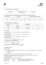
1.3 - Identification code for multiple pumps identification code front pump identification code intermediate pump (omit for double pumps) identification code rear pump 1.4 - Compatibility among mounting flange, type of shaft and type of hydraulic connection FLANGE CODE SHAFT CODE HYDRAULIC CONNECTION CODE 1.5 - Identification code for mating joints SECOND PUMP FIRST PUMP a) single pump size 1 - 1,3 cm /rev - anticlockwise rotation - standard flange and shaft GP1-0013L97F/20N 3 b) single pump size 2 - 14 cm /rev - clockwise rotation - standard flange and shaft GP2-0140R97F/20N 3 c) single pump...
Open the catalog to page 3
2.3 - Degree of fluid contamination The maximum degree of fluid contamination must be according to ISO 4406:1999 class 20/18/15; therefore, use of a filter withβ20 ≥75 is recommended. A degree of maximum fluid contamination according to ISO 4406:1999 class 18/16/13 is recommended for optimum endurance of the pump. Hence, use of a filter with β10 ≥100 is recommended. If there is a filter installed on the suction line, be sure that the pressure at the pump inlet is not lower than the values specified in paragraph 13. The suction filter must be equipped with a by-pass valve and, if possible, with...
Open the catalog to page 4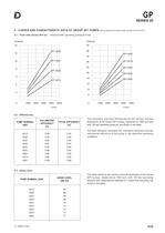
SERIES 20 4 - CURVES AND CHARACTERISTIC DATA OF GROUP GP1 PUMPS 4.1 - Flow rate curves Q=f (n) (values obtained with mineral oil with viscosity of 36 cSt at 50°C) obtained with operating pressure 0 bar 4.2 - Efficiencies PUMP NOMINAL SIZE VOLUMETRIC EFFICIENCY [%] TOTAL EFFICIENCY [%] The volumetric and total efficiencies for the various nominal dimensions of the Group GP1 pumps, measured at 1500 rpm and with 150 bar operating pressure, are shown in the table. The total efficiency considers the volumetric efficiency and the mechanical efficiency of the pump in the specified operating conditions....
Open the catalog to page 5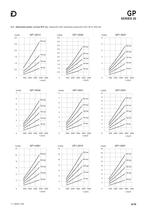
4.4 - Absorbed power curves N=f (n), measured with operating pressures from 50 to 250 bar
Open the catalog to page 6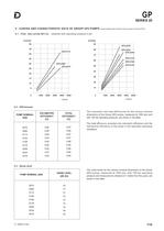
SERIES 20 5 - CURVES AND CHARACTERISTIC DATA OF GROUP GP2 PUMPS 5.1 - Flow rate curves Q=f (n) (values obtained with mineral oil with viscosity of 36 cSt at 50°C) obtained with operating pressure 0 bar PUMP NOMINAL SIZE VOLUMETRIC EFFICIENCY [%] TOTAL EFFICIENCY [%] The volumetric and total efficiencies for the various nominal dimensions of the Group GP2 pumps, measured at 1500 rpm and with 150 bar operating pressure, are shown in the table. The total efficiency considers the volumetric efficiency and the mechanical efficiency of the pump in the specified operating conditions. PUMP NOMINAL SIZE...
Open the catalog to page 7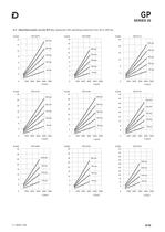
5.4 - Absorbed power curves N=f (n), measured with operating pressures from 50 to 250 bar
Open the catalog to page 8
SERIES 20 6 - CURVES AND CHARACTERISTIC DATA OF GROUP GP3 PUMPS 6.1 - Flow rate curves Q=f (n) (values obtained with mineral oil with viscosity of 36 cSt at 50°C) obtained with operating pressure 0 bar PUMP NOMINAL SIZE VOLUMETRIC EFFICIENCY [%] TOTAL EFFICIENCY [%] The volumetric and total efficiencies for the various nominal dimensions of the Group GP3 pumps, measured at 1500 rpm and with 150 bar operating pressure, are shown in the table. The total efficiency considers the volumetric efficiency and the mechanical efficiency of the pump in the specified operating conditions. PUMP NOMINAL SIZE...
Open the catalog to page 9
6.4 - Absorbed power curves N=f (n), measured with operating pressures from 50 to 250 bar
Open the catalog to page 10
SERIES 20 7 - GROUP GP1 PUMPS OVERALL AND MOUNTING DIMENSIONS with standard flange dimensions in mm tapered shaft end (standard, identification code 7) -0.02 -0.05 4 holes rectangular mounting flange 6.5 (standard, identification code 9) flanged ports (standard, identification code F) drainage port 1/4” BSP on reversible pump only also available with BSP ports (identification code B) pump nominal dimension 1 suction port clockwise 2 delivery port clockwise rotation rotation flange BSP flange BSP cylindrical with key shaft end (identification code: 5) NOTE: 1. On pumps with anticlockwise rotation...
Open the catalog to page 11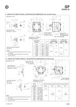
SERIES 20 9 - GROUP GP2 PUMPS OVERALL AND MOUNTING DIMENSIONS with standard flange M tapered shaft end (standard, id. code 7) 4 holes rectangular mounting flange (standard, id.code 9) drainage port 1/4” BSP on reversible pump only 16.5 pump nominal dimension cylindrical with key shaft end (id code: 5) NOTE: 1. On pumps with anticlockwise rotation the ports (1) and (2) are reversed 2. On reversible pumps the delivery port has the same size of the suction flanged ports (standard, code F) also available with BSP ports id.code B) 40 1 suction port clockwise rotation flange BSP Ø13 2 delivery port...
Open the catalog to page 12All Duplomatic Oleodinamica catalogs and technical brochures
 Energy eng
4 Pages
 Full catalogue
1289 Pages
 PZM2
PZM22 Pages
 IGP INTERNAL GEAR PUMPS
20 Pages
 1P EXTERNAL GEAR PUMPS
4 Pages
 Mobile eng
3 Pages
 Industrial eng
5 Pages
 Machine tool eng
6 Pages
 Metal forming eng
6 Pages
 Mobile eng
2 Pages
 Leaflet Axes Control System
2 Pages
- ERLO manual valve
- ERLO control valve
- ERLO ball valve
- Cylinder
- ERLO solenoid valve
- Regulating valve
- Flap valve
- Check valve
- ERLO 2-way solenoid valve
- Directional control valve
- Double-acting cylinder
- Hydraulic pump
- Hydraulic cylinder
- Oil valve
- Hydraulic valve
- 2-channel valve
- ERLO signal amplifier
- Electrically-actuated valve
- Hydraulic directional control valve