

TRM-S
1 /18Pages

TRM-S
1 /18Pages
Catalog excerpts

DUPLOMATIC AUTO M ATI O N TRM-S sries 20 VERTICAL AXIS SERVOMOTOR TURRETS TOOLHOLDERS CI-AMPING DIN 69881-1 *«* - lONet - CERTIFICATS TECHNICAL INFORMATION I.T. 6444 ISSUED 02-09 The data given in the I.T. are subject to technical modifications without notice.
Open the catalog to page 1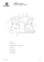
TRM-S / sries 20 INTERNAL KINEMATIC MOTION DUPLOMATIC automation 1) Tool post 2) Front coupling 3) Hydraulic clamping / unclamping system 4) Gear box 5) Servomotor 6) Control switches 7) Coolant valves I.T.6444-0209 A2-2
Open the catalog to page 2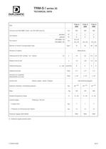
TRM-S / sries 20 TECHNICAL DATA DUPLOMATIC Size TRM-S 250 TRM-S 320 TRM-S 400 Tool post size DIN 69881 sheet 1 (ex VDI 3425 sheet 5) mm 250 320 400 Tool stations standard N° 4 4 4 optional N° 6 6 6 Tool section DIN 69881-115 DIN 69881-140 mm 32 x 32 40 x 40 40 x 40 40 x 40 Moment of inertia of transportable mass Kgm 2 10 25 60 100 Direction of rotation Bidirectional Indexing time for 90° (unclap. - rot. - clamp.) (1) s 1,8 2,2 2,5 2,9 Rotation time for 90° s 1,0 1,25 1,6 2,0 Indexing frequency a = 90° cycle/min 8 6 5 4 Indexing accuracy Deg° ± 4" ± 4" ± 4" Precisione di ripetibilit Repeatability...
Open the catalog to page 3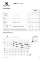
TRM-S / sries 20 DUPLOMATIC autqmation Loading capacity F1 T b Max. tangential torque F1xb Nm 250 TRM-S 320 400 6.300 13.000 25.000 6.900 19.000 35.000 4.500 10.000 17.000 130 250 450 130 230 350 Max. tilting torque (to push) F2xb Nm b j Max. tilting torque (to lift) F3xb Nm 3. Unbalancing torque with horizontal axis PxL Nm L Kg Transportable mass with vertical axis and load gravity centre on the rotation axis Duty performances (F1) 200000 100000 80000 60000 40000 20000 10000 8000 6000 4000 2000 1000 0 100 200 300 400 500 600 700 b [mm] I.T.6444-0209 A2-4
Open the catalog to page 4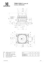
TRM-S 250-4 / sries 20 OVERALL DIMENSIONS DUPLOMATIC automation t 291 DIN 69881-1** (vedi tab. 1) 8 (see tab. 1) v_ u o o 0)|| -i-<M<M A-B Hydralic connections 3/8" GAS L 闗 Drain 1/8" GAS R (or R1) coolant inlet 3/8" GAS U ח (or U1 ) coolant outlet 3/8" GAS E Internal coolant outlet C ח PG 13,5 for electrical connections D Holes for pins 0 16 Tab. 1 E F G H DIN 69881-115 115 65 50 125 DIN 69881-140 140 80 60 130 I.T.6444-0209 A2-6
Open the catalog to page 6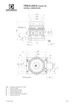
TRM-S 250-6 / sries 20 OVERALL DIMENSIONS DUPLOMATIC autqmatiqn 0 291 0 250 o A-B Hydralic connections 3/8" GAS L 闗 Drain 1/8" GAS R Coolant inlet 3/8" GAS U ח Coolant outlet 3/8" GAS E Internal coolant outlet C ח PG 13,5 for electrical connections D Holes for pins 0 16 I.T. 6444-0209 A2-7
Open the catalog to page 7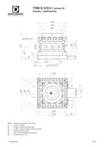
TRM-S 320-4 / sries 20 OVERALL DIMENSIONS DUPLOMATIC automation 0 364 m 320 0270 A-B Hydralic connections 1/2" GAS L 闗 Drain 1/4" GAS R (or R1) coolant inlet 3/8" GAS U ח (or U1 ) external coolant outlet 3/8" GAS E Internal coolant outlet C ח PG 13,5 for electrical connections D Holes for pins 0 16 I.T.6444-0209 A2-8
Open the catalog to page 8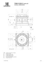
TRM-S 320-6 / sries 20 OVERALL DIMENSIONS DUPLOMATIC autqmatiqn 0 364 o o"1 + DIN 69881-140 t 352 4 8 3 5 u m coin Il II i II Working position i 345 ! 384 = T = 108 A-B Hydralic connections 1/2" GAS L 闗 Drain 1/4" GAS R Coolant inlet 3/8" GAS U ח Coolant outlet 3/8" GAS E Internal coolant outlet C ח PG 13,5 for electrical connections D Holes for pins 0 16 I.T.6444-0209 A2-9
Open the catalog to page 9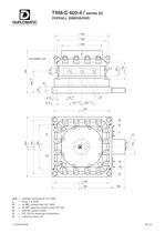
TRM-S 400-4 / sries 20 OVERALL DIMENSIONS DUPLOMATIC autqmation <P 444 $ 400 4 4 ^ 484 A-B 霗 Hydralic connections 1/2" GAS L Drain 1/4" GAS R ח(or R1) coolant inlet 3/4" GAS U (or U1 ) external coolant outlet 3/4" GA E ח Internal coolant outlet C PG 13,5 for electrical connections D ח Holes for pins 0 16 I.T.6444-0209 A2-10
Open the catalog to page 10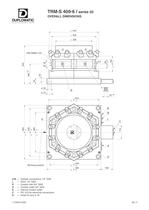
TRM-S 400-6 / sries 20 OVERALL DIMENSIONS DUPLOMATIC autqmatiqn 0 444 0 400 00 ^ 484 A-B Hydralic connections 1/2" GAS L 闗 Drain 1/4" GAS R Coolant inlet 3/4" GAS U ח Coolant outlet 3/4" GAS E Internal coolant outlet C ח PG 13,5 for electrical connections D Holes for pins 0 16 I.T.6444-0209 A2-11
Open the catalog to page 11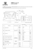
TRM-S / sries 20 WIRING DIAGRAM DUPLOMATIC autqmation The TRM-S* turrets are supplied with the DDC* Control Unit that drivers the complte indexing cycle and that must be installed inside the machine electrical cabinet. The turret-side electrical connections are carried-out by terminal boards, inside the connections box. REF. COMPONENT CHARACTERISTICS WIRING NUMBER SIGNALS SIMBOLS COLOUR SERVOMOTOR WHITE BLUE RED W V U © THERMAL DETECTOR 100 C 1,5A 250V OUTPUT - NC _ 10 15 BLUE BLUE + 24 V MOTVL © RESOLVER il -J ) - 騗 1 2 3 f 4 WHITE / RED WHITE / BLACK RED BLACK YELLOW BLUE RPOW RPOWG RSIN RSING...
Open the catalog to page 12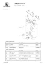
POWER CONNECTORS CABLE SIDE CODE CN10/X6 AC supply 3 ~ PC4/3-ST-762 0680931 CN11/X7 Motor power Phoenix contact PC4/4-ST-762 0680932 TE/PE Ground connections Faston 6,3 mm not supplied SIGNAL CONNECTORS CABLE SIDE CODE CN1 Digital OUTPUTS 20 pins/2 Rows IDC-2,54 mm female DIN 41651 not supplied CN2 Digital INPUTS 16 pins/2 Rows IDC-2,54 mm female DIN 41651 not supplied CN3 24VDC for I/O section Phoenix contact FK-MCP 1,5/2-STF-3,5 0680934 CN8 24VDC for driver section Phoenix contact FK-MCP 1,5/2-STF-3,5 0680934 CN7 Signal to/from turret SUB-D 25 female DIN 41652 not supplied CN9 RS232 serial...
Open the catalog to page 14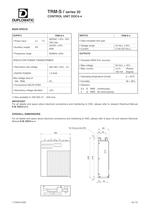
TRM-S / sries 20 CONTROL UNIT DDC4-* DUPLOMATIC automation MAIN SPECS SUPPLY TRM-S-* Power input 3~ (1) 400VAC +15% -10% 18A max 镕 Auxiliary supply DC 24VDC ±10% 35W Frequency range 50/60Hz ±2Hz SPECS FOR POWER TRANSFORMER: Օ Secondary rate voltage 400 VAC ±10% - 3~ RATED POWER 1,2 KVA Max voltage drop at 18A RMS 5% Օ Connections DELTA STAR Secondary voltage deviation ±2% INPUTS TRM-S-* Օ Opto-insulated sink type Voltage range 24 Vd.c. ±10% Օ Current 5 mA (24 Vd.c.) OUTPUTS Transistor MOS N.O. (source) Օ Max voltage 24 Vd.c. ± 10% Max. current 2,0 A (Power) 100 mA (Signal) Օ Operating temperature...
Open the catalog to page 15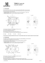
TRM-S / sries 20 COOLANT CIRCUIT DUPLOMATIC "4" POSITIONS Each turret has two inlets for the coolant, respectively R and R1, fitted on the base plate. The coolant passes from the base to the turret housing through the two valves V and V1. On the tool post the coolant outles are: External coolat through the outlet holes on the top of tool post R 镗 U ; R1 U1. ו Internal coolat directly on the tool hoolder through the valves E. el -~-, Valve E* e3 fig. 2 fig. 3 fig. 4 The working of the valve "E" is sketched on the fig. 3 and 4. Fig. 3 without toolholders (closed valve) Fig. 4 with toolholders...
Open the catalog to page 16All Duplomatic Automation catalogs and technical brochures
 TMY-BR (BA)
20 Pages
 DM-TR* series
24 Pages
 ELECTROSPINDLE
8 Pages
 BME
BME4 Pages
 BSV-N
BSV-N20 Pages
 SM(A)
SM(A)24 Pages
 DM
DM18 Pages
 TRM-N
TRM-N20 Pages
 SM-BR
SM-BR30 Pages
 MDT
MDT22 Pages
 ODT-N
ODT-N24 Pages

- Chuck
- Milling chuck
- Machining tool holder
- Collet tool holder
- Milling tool holder
- Rotary indexing table
- Tapping holder
- Horizontal rotary indexing table
- Machine tool rotary indexing table
- VDI chuck
- VDI tool holder
- Tool turret
- CAPTO chuck
- BMT tool holder
- Disc tool turret
- CAPTO tool holder
- Machining center tool holder
- Hydraulic tool turret
- Direct-drive rotary indexing table
- Servo-driven tool turret